EasyManuals Logo

IBM StorVize V7000 Gen2 User Manual

IBM StorVize V7000 Gen2
188 pages
To Next Page IconTo Next Page
To Previous Page IconTo Previous Page
Page #71 background imageLoading...
Page #71 background image
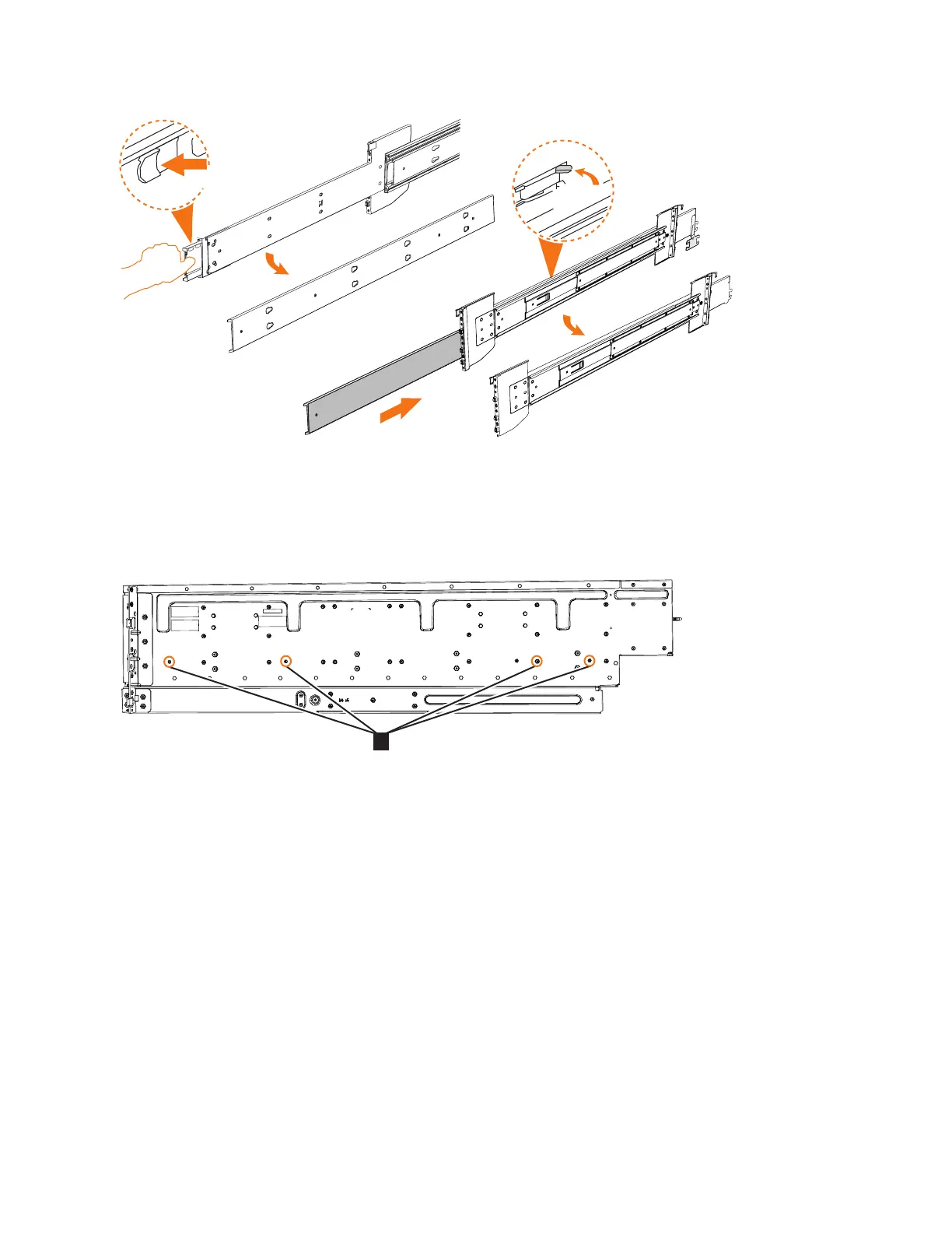
4. Use four M4 screws to attach the inner rail to the side of the enclosure.
Figure 36 shows the screw locations.
5. Install the inner section of the rail onto each side of the expansion enclosure, as
shown in Figure 37 on page 48.
Pull tab forward
(a)
Push
x2
svc01080
Figure 35. Detaching the inner rail section
svc00965
1
Figure 36. Screw locations to attach the inner rail to the enclosure
Chapter 2. Installing the Storwize V7000 Gen2 and Storwize V7000 Gen2+ hardware 47

Table of Contents

Questions and Answers:

Question and Answer IconNeed help?

Do you have a question about the IBM StorVize V7000 Gen2 and is the answer not in the manual?

IBM StorVize V7000 Gen2 Specifications

General IconGeneral
CategoryStorage
Maximum Drives504
RAID Levels0, 1, 5, 6, 10
Operating SystemIBM Spectrum Virtualize
Power SupplyDual redundant power supplies
Input Voltage100-240 V AC
Humidity8% to 80% non-condensing
ModelStorwize V7000 Gen2
Drive InterfaceSAS
Form Factor2U
Drive Types SupportedSAS SSDs, SAS HDDs
Host Interface8 Gb FC, 16 Gb FC, 10 Gb iSCSI
Nodes2
Operating Temperature10°C to 35°C
Non-operating Temperature-10°C to 50°C

Related product manuals