v The expansion enclosure is removed from the rack, as described in “Removing
an expansion enclosure from a rack: 2076-92F” on page 92.
v A lift is supporting the weight of the enclosure.
v The top cover, fans, drives, and other heavy FRUs are removed from the
enclosure.
About this task
The 2076-92F expansion enclosure contains two fan interface boards (FIBs). The
FIBs act as the interface between the fans and the system drive board. FIB 1
connects fan modules 1 and 2 to the drive board; FIB 2 connects fan modules 3
and 4. If the fault LED on each fan module is lit, it is possible that the FIB that
controls those modules needs to be replaced. You can also issue the
lsenclosurefanmodule command to display the status of the fans.
If you removed the FIBs from a faulty expansion enclosure, you must reinstall
them in the replacement enclosure. Refer to the procedure described in “Replacing
an enclosure: 2076-92F” on page 116.
Procedure
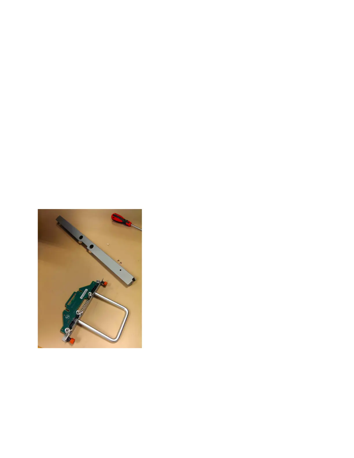
1. Assemble the new FIB, cover, and the cover screws (shown in Figure 83) in a
safe location.
2. Carefully insert the new FIB into the expansion enclosure chassis, as shown in
Figure 84 on page 91.
Figure 83. FIB parts for the chassis
90 Storwize V7000 Gen2 and Gen2+: Quick Installation Guide

 Loading...


