Options applicable to control enclosures
Note: All options other than cables are preinstalled.
__ v 64 GB main memory upgrade
__ v Cache memory upgrade
__ v Four-port 8 Gbps Fibre Channel host interface adapter with two small
form-factor pluggable (SFP) transceivers installed
__ v Fibre Channel cables
__ v SAS cables
__ v Four-port 10 Gbps iSCSI / FCoE host interface adapter
__ v Compression accelerator
__ v Drives
__ v Power cords for connection to wall sockets
__ v Four-port 16 Gbps Fibre Channel HBA pair
__ v Four-port 10 Gbps Ethernet HBA pair
__ v Compression Accelerator card pair
Options applicable to expansion enclosures
Note: All options other than cables are preinstalled.
__ v Expansion enclosure attachment cables
__ v Drives
__ v Power cords for connection to wall sockets
Identify the hardware components
The following graphics identify the hardware components and port locations for
the control enclosure and expansion enclosure on Storwize V7000 systems.
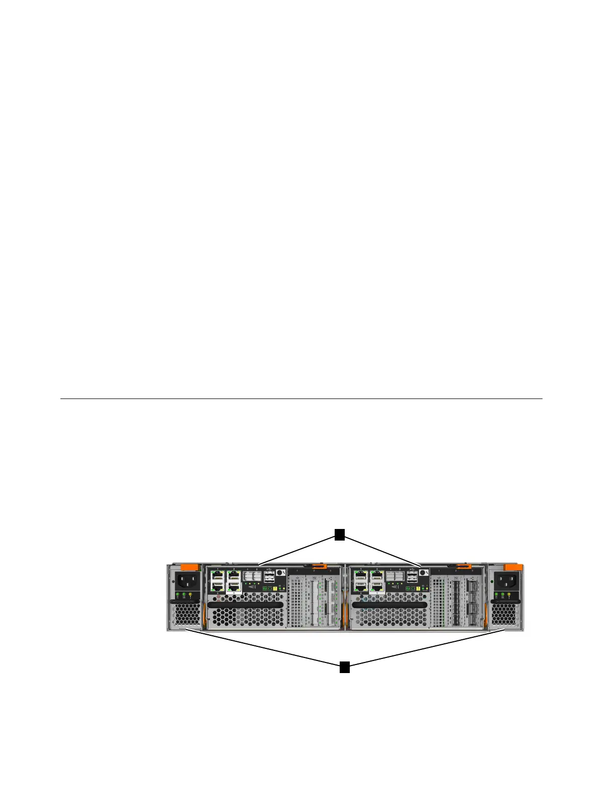
Control enclosure components
Figure 1 shows the rear view of a control enclosure and identifies the location of
the power supply units and node canisters.
v ▌1▐ Node canisters
v ▌2▐ Power supply units
Figure 1. Rear view of a Storwize V7000 control enclosure
6 Storwize V7000 Gen2 and Gen2+: Quick Installation Guide

 Loading...


