Note any LEDs that are lit, and then reinstall the light path diagnostics panel in
the server.
Look at the system service label inside the server cover, which gives an
overview of internal components that correspond to the LEDs on the light path
diagnostics panel. This information and the information in “Light path
diagnostics” on page 124 can often provide enough information to diagnose the
error.
3. Remove the server cover and look inside the server for lit LEDs. Certain
components inside the server have LEDs that are lit to indicate the location of a
problem.
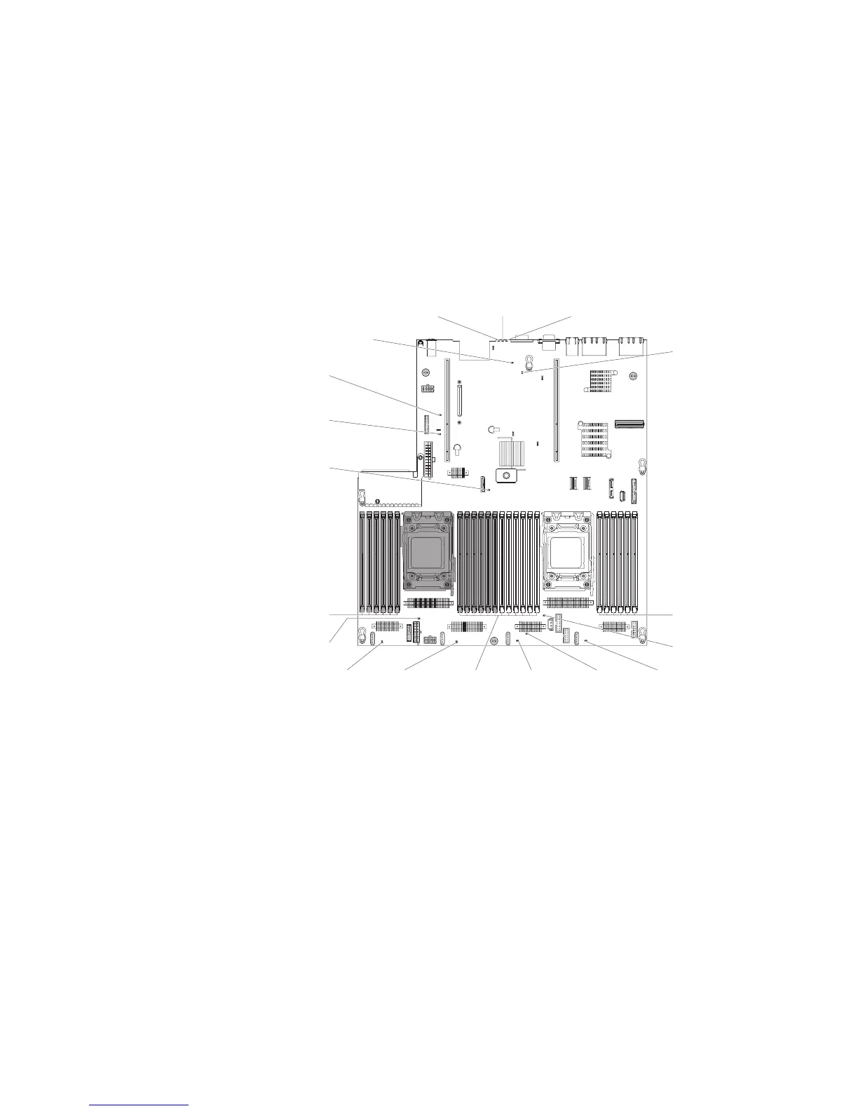
The following illustration shows the LEDs on the system board.
System Error
LED
Locator LED Power LED
10G Ethernet card
error LED
Imm2 heartbeat
LED
Enclosure management
heartbeat LED
Standby power
LED
Battery
error LED
Fan 4
error LED
Fan3
error LED
Microprocessor 2
error LED
Fan2
error LED
Fan1
error LED
Microprocessor 1
error LED
System board
error LED
DIMM 19-24
error LED
(under the latches)
DIMM 1-6
error LED
(under the latches)
DIMM 7-18
error LED
(under the latches)
If an error occurs, view the light path diagnostics LEDs in the following order:
1. Look at the operator information panel on the front of the server.
v If the check log LED is lit, it indicates that an error or multiple errors have
occurred. The sources of the errors cannot be isolated or concluded by
observing the light path diagnostics LEDs directly. A further investigation into
IMM2 system-event log or system-error log might be required.
v If the system-error LED is lit, it indicates that an error has occurred; go to
step 2 on page 127.
The following illustration shows the operator information panel.
126 IBM System x3650 M4 Type 7915: Problem Determination and Service Guide

 Loading...


