a. Close the microprocessor retainer on the microprocessor socket.
b. Identify which release lever is labeled as the first release lever to close and
close it.
c. Close the second release lever on the microprocessor socket.
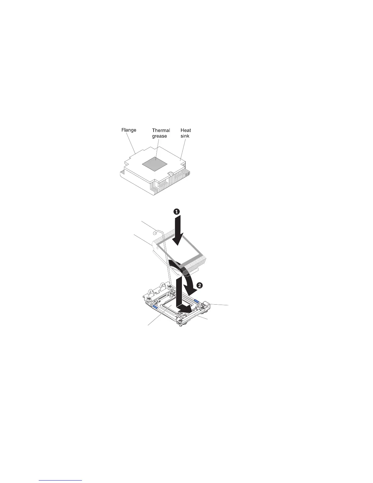
10. Install the heat sink:
Attention:
v Do not set down the heat sink after you remove the plastic cover.
v Do not touch the thermal grease on the bottom of the heat sink after you
remove the plastic cover. Touching the thermal grease will contaminate it.
See “Thermal grease” on page 287 for more information.
Retainer bracket
Heat sink
release lever
Lock tab
Microprocessor
Heat sink
a. Remove the plastic protective cover from the bottom of the heat sink.
b. Position the heat sink over the microprocessor. The heat sink is keyed to
assist with proper alignment.
c. Align and place the heat sink on top of the microprocessor in the retention
bracket, thermal material side down.
d. Press firmly on the heat sink.
e. Rotate the heat sink release lever to the closed position and hook it
underneath the lock tab.
11. If you installed the second microprocessor, install the fourth fan (see “Installing
a hot-swap dual-motor hot-swap fan” on page 258).
12. Reinstall the air baffle (see “Installing the air baffle” on page 208).
13. Install the cover (see “Installing the cover” on page 206).
14. Slide the server into the rack.
286 IBM System x3650 M4 Type 7915: Problem Determination and Service Guide

 Loading...


