Section 9 - Fault Finding
104 Installation and Maintenance
FAULT FINDING
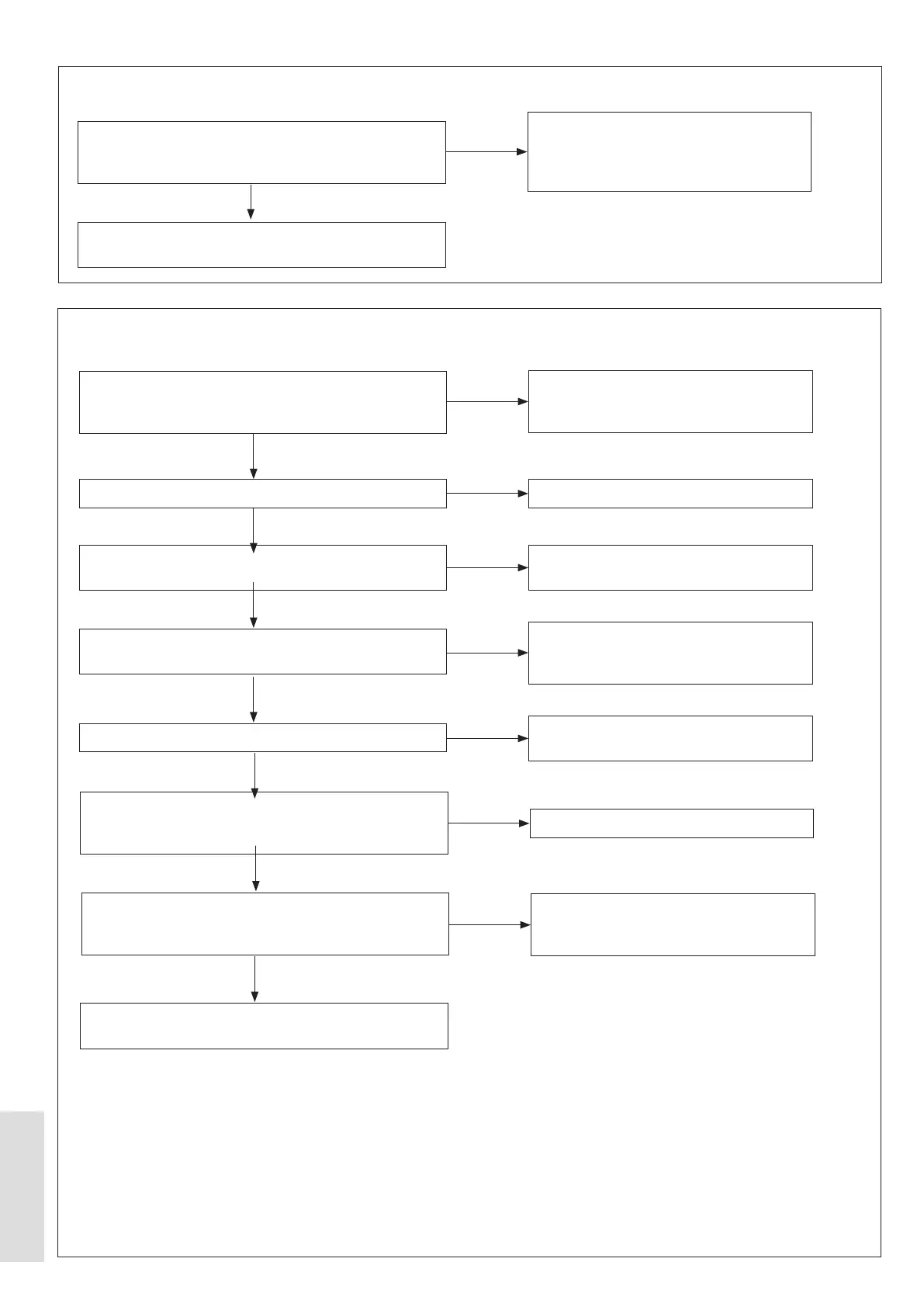
9.1.24 Inverter not matched to Outdoor PCB dip switch setting Error
9.1.25 Low Pressure Error
Are DIP switches 1 to 4 on S5 set to OFF, Figure 67 on
page 116 item 10, and DIP switches 1 to 4 on S6 are
set to the capacity of the Heat Pump?
Replace the Outdoor PCB. If the fault does not change,
replace the Inverter PCB.
Make sure that DIP switches 1 to 4 on S5
are set to OFF. Figure 67 on page 116
items 10, and DIP switches 1 to 4 on S6
are set to the capacity of the Heat Pump?
NO
YES
Does Line 15 (P1 comp. pressure), equal Line 16 (P2
comp. pressure)? (refer to 5.8.6.1 Unit Status, Operation
Parameter).
Is the Outdoor Unit covered with Snow or Ice?
Is the Air to Refrigerant Heat Exchanger blocked or
dirty?
to supply good ventilation?
Does the Fan operate correctly?
During normal operation, are there vibrations from the
body of the electronic expansion valve with a click when
it is set to ON or OFF?
Is the wiring assembly to the Electronic Expansion Valve
connected correctly?
Refer to Figure 67 on page 116.
Replace the Outdoor PCB. If the fault does not change,
then replace the Low Pressure sensor.
Replace the Outdoor PCB. If the fault does
not change, replace the Low Pressure
sensor.
Remove the Snow and/or Ice.
Remove the blockage from the Air to
Refrigerant Heat Exchanger, then clean it.
Make sure that there are no obstacles
outdoor unit.
Replace the Fan motor. If the fault does
not change, then replace the Inverter PCB.
Recharge the refrigerant.
Make sure that the wiring assembly from
the Electronic Expansion Valve to CN33 /
EEV1 is connected correctly.
NO
YES
YES
NO
NO
NO
NO
YES
NO
YES
YES
YES
YES
YES