Section 9 - Fault Finding
109
Installation and Maintenance
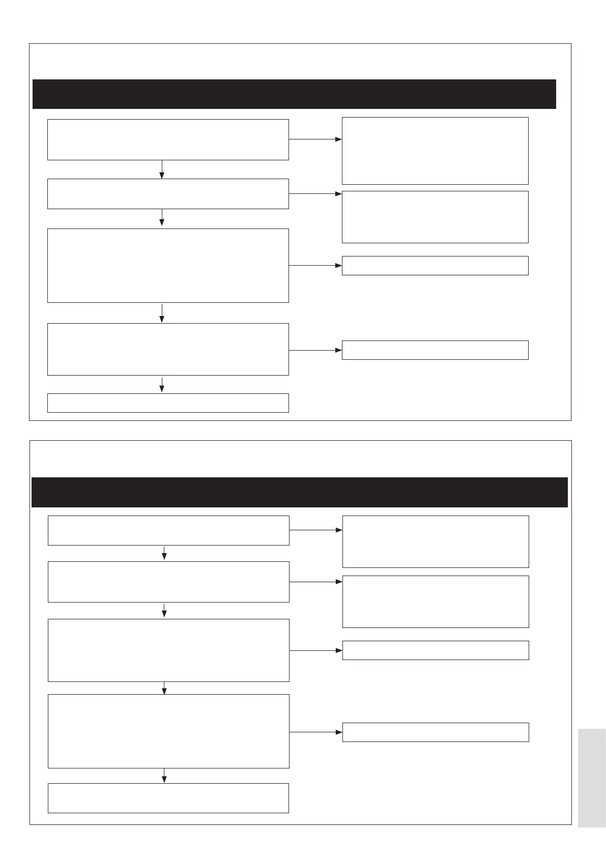
FAULT FINDING
Is there a 240 V AC supply voltage connected to the
Inverter PCB?
Refer to Figure 67 on page 116.
Is the wiring assembly from the Fan connected correctly
to the Fan and the Inverter?
Is the Modbus wiring assembly connected to both the
Outdoor PCB and the Inverter PCB?
Is the 7-way wiring assembly correctly attached to the
Inverter and the Outdoor PCB?
Refer to Figure 67 on page 116.
Disconnect the wiring assembly from the Compressor.
Measure the resistances at the terminals. The
- U to V,
- U to W, and
- V to W.
Disconnect the Fan. Are the terminal resistances at the
Fan the same as those as shown below::
Disconnect the wiring assemblyfrom the Inverter to the
Compressor. Connect the wiring assembly from the
Inverter to the Inverter Tester. Test the Inverter. Is the
Inverter defective?
Disconnect the Compressor. Are the terminal
resistances at the Compressor the same as those
shown below:
Replace the Outdoor PCB.
If the fault continues and the error codes L45, J45), and
J61 are seen, the replace the Fan.
Make sure that the mains wiring assembly
supply and is not damaged.
Connect the mains wiring assembly to the
Inverter PCB.
Refer to the applicable wiring diagram.
Make sure that the wiring assembly from
the Fan is connected correctly to the Fan
and the Inverter.
Make sure that the Modbus wiring
assembly is not damaged and is correctly
connected to both the Outdoor PCB and
the Inverter PCB.
Refer to the applicable wiring diagram.
Make sure that the wiring assembly from
Modbus s connected correctly to the
Inverter and the Outdoor PCB.
Replace the Compressor.
Replace the Fan.
Replace the Inverter.
Replace the Inverter.
NO
NO
NO
NO
NO
NO
NO
NO
YES
YES
YES
YES
YES
YES
YES
YES
9.1.33 Wrong Fan Fitted (L45) and Wrong Fan Motor Fitted (J45) and Fan Connections Short Circuit (J61)
ᘐ WARNING: Set the power supply to OFF. Wait for a minimum of 10 minutes before you work on the appliance. This is
to let harmful electrical charges decrease to below a safe limit.
9.1.32 Inverter High Temperature (L2E and LC9)
ᘐ WARNING: Set the power supply to OFF. Wait for a minimum of 10 minutes before you work on the appliance. This
is to let harmful electrical charges decrease to below a safe limit.



 To Next Page