Section 9 - Fault Finding
114 Installation and Maintenance
FAULT FINDING
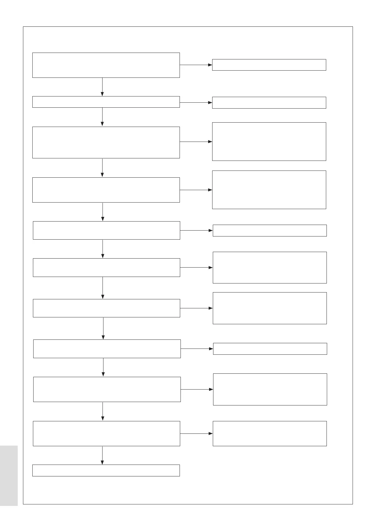
Is the CH Zone 2 scheduled to be ON?
Refer to Schedule, Zone 2 daily timer or Zone 2 weekly
schedule in Appendix 1.3.1)
Is Room Stat 2 set to ON?
Disconnect the ON/OFF Room Stat 2 connector from
the Indoor Control Box. Can electrical continuity be
measured across the ends of the wiring assembly
connected to the room thermostat?
Is the wiring assembly at CN31 on the Indoor PCB,
connected correctly to the Internal Control Box? Refer to
Figure 46. Control Box - Internal Wiring on page 46.
Is there a 240 V AC supply voltage at the Indoor PCB,
9_Pc connection?
Is there a 240 V AC supply voltage at the CH2 Relay
Coil LIVE connection?
Is there a 240 V AC supply voltage at the CH2 Relay
contact L-in connection?
Is there a 240 V AC supply voltage at the CH2 Relay
contact L-out?
Is there a 240 V AC at the
CH2 Pump or Valve LIVE (L) connection? Refer to
Figure 46. Control Box - Internal Wiring on page 46.
Is there a 240 V AC supply voltage at the CH2 Pump?
Refer to Figure 46. Control Box - Internal Wiring on
page 46.
Replace the Pump.
Replace the Indoor PCB.
Set Room Stat 2 to ON.
Make sure that the wiring assembly from
the Room Stat to the Indoor Control
Box is connected correctly. Has the fault
changed? If the fault continues, then
replace the room thermostat?
Make sure that the wiring assembly at
CN31 on the Indoor PCB, is connected
correctly to the Internal Control Box. Refer
to Figure 46. Control Box - Internal Wiring
on page 46.
Replace the Indoor PCB.
Make sure that the wiring assembly from
the Indoor PCB, 9_Pc connection, is
correctly connected to the CH2 Relay Coil
LIVE connection.
Make sure that the wiring assembly from
the mains electrical supply is correctly
connected to the CH2 Relay Contact L-out
connection.
Replace the Control Box.
Make sure that the wiring assembly from
the CH2 Relay Contact L-out connector to
the CH1 Pump or Valve LIVE connector is
connected correctly.
Make sure that the wiring assembly
between the Control Box and the CH2
Pump is correctly connected.
NO
NO
NO
NO
NO
NO
NO
NO
NO
NO
YES
YES
YES
YES
YES
YES
YES
YES
YES
YES
9.1.38 No CH2 Pump



 To Next Page