IDEC SmartRelay functions
IDEC SmartRelay Manual 120
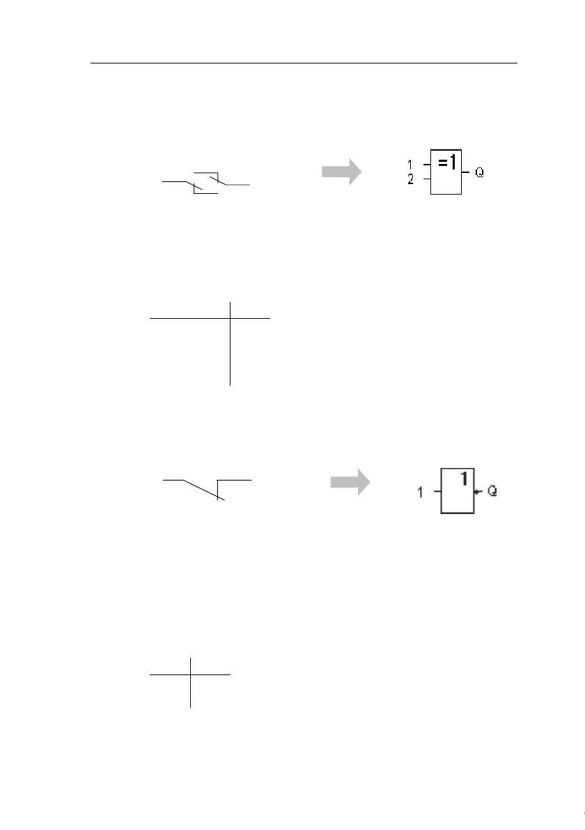
4.2.7 XOR (exclusive OR)
Symbol in IDEC SmartRelay:
The XOR in a circuit diagram,
shown as series circuit with 2
changeover contacts:
The output status of the XOR is 1 if the inputs are not equiv-
alent.
At an unused block input (x): x = 0.
Table of the XOR logic
4.2.8 NOT (Negation, Inverter)
Symbol in IDEC SmartRelay:
A normally closed contact in
the circuit diagram:
The output status is 1 if the input is 0. The NOT block inverts
the input status.
Advantage of the NOT block, for example: The IDEC
SmartRelay does not require normally closed contacts. You
simply use a normally open contact and the NOT block to
convert these into a normally closed contact.
Table of the NOT logic
12Q
000
011
101
110
1Q
01
10
Courtesy of Steven Engineering, Inc. ● 230 Ryan Way, South San Francisco, CA 94080-6370 ● General Inquiries: (800) 670-4183 ● www.stevenengineering.com
 Loading...