IDEC SmartRelay installation and wiring
IDEC SmartRelay Manual 26
2.3 Wiring IDEC SmartRelay
Wire IDEC SmartRelay using a screwdriver with a 3-mm
blade.
You do not need wire ferrules for the terminals. Permitted
conductor cross-sections:
• 1 x 2.5 mm
2
• 2 x 1.5 mm
2
for each second terminal chamber
Tightening torque: 0.4...0.5 Nm or 3...4 lbs in
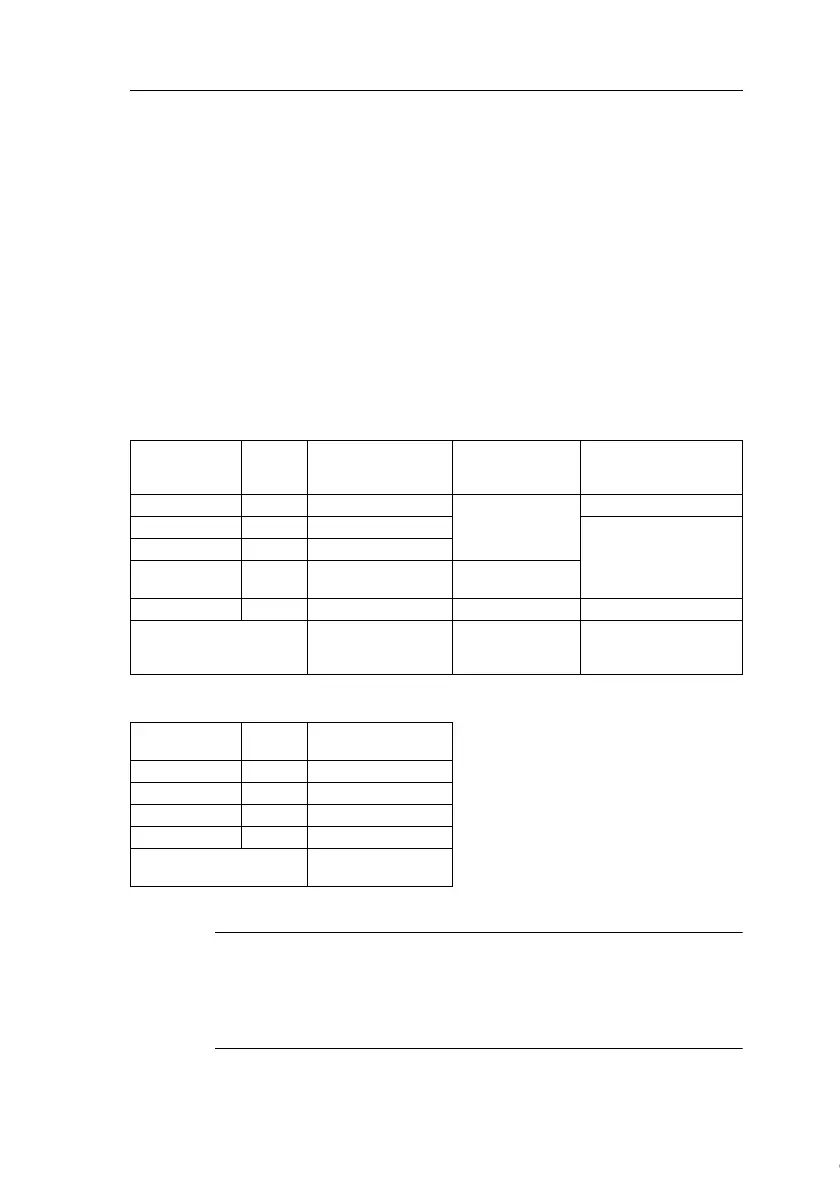
Recommended ferrules
Ferrules order No.
For 1-cable connection
For 2-cable connection
Note
Always cover the terminals after you have completed the installa-
tion. To protect IDEC SmartRelay adequately from impermissible
contact to live parts, local standards must be complied with.
Cross-section
[mm
2
]
AWG
Phoenix Contact
Ferrule type No.
NIC HIFU
Blade Terminals
type No.
NIC HIFU
Insulated Pin Terminals
type No.
0.3 22 AI0,5-10WH
BT1.25-10-1
−
0.5 20 AI0,5-10WH
TGN-TC-1.25-11T
0.75 18 AI0,75-8GY
1.25 18 AI1,5-8BK
BT1.25-10-1
BT2-9-1
2.0 16 AI2,5-8BU BT2-9-1 −
Recommended
crimping tool
CRIMPFOX ZA 3
NH1
NH61
NH11
NH32
NH65
Cross-section
[mm
2
]
AWG
Phoenix Contact
Ferrule type No.
0.3 22 AI-TWIN2X0,5-8WH
0.5 20 AI-TWIN2X0,5-8WH
0.75 18 AI-TWIN2X0,75-8GY
1.25 18 AI-TWIN2X1,5-8BK
Recommended
crimping tool
CRIMPFOX ZA 3
Courtesy of Steven Engineering, Inc. ● 230 Ryan Way, South San Francisco, CA 94080-6370 ● General Inquiries: (800) 670-4183 ● www.stevenengineering.com
 Loading...