IDEC SmartRelay functions
189
IDEC SmartRelay Manual
4.4.19 Analog value monitoring
Short description
This special function saves the process variable of an analog
input to memory, and sets the output when the output vari
-
able exceeds or drops below this stored value plus a config-
urable offset.
* AI1...AI8:0...10 V corresponds with 0...1000 (internal val-
ue).
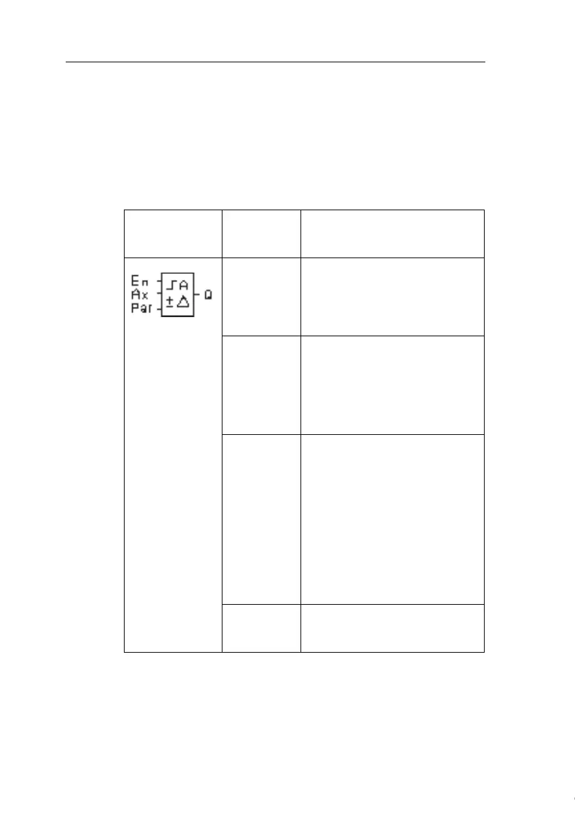
Symbol in
IDEC
SmartRelay
Wiring Description
Input En A positive edge (0 to 1 transition)
at input En saves the analog val-
ue at input Ax (“Aen”) to memory
and starts monitoring of the ana-
log range Aen
±∆.
Input Ax You apply the analog signal to
be monitored at input Ax.
Use the analog inputs AI1...AI8
(
*
)
, the Analog Memory Markers
AM1...AM6, the block number of
a function with analog output.
Parameter A: Gain
Range of values:
±10.00
B: Offset
Range of values:
±10,000
∆: Difference value for the
Aen on/off threshold
Range of values: ±20,000
p: Number of decimals
Range of values:
0, 1, 2, 3
Output Q Q is set/reset, depending on the
stored analog value and the off-
set.
Courtesy of Steven Engineering, Inc. ● 230 Ryan Way, South San Francisco, CA 94080-6370 ● General Inquiries: (800) 670-4183 ● www.stevenengineering.com
 Loading...