IDEC SmartRelay functions
171
IDEC SmartRelay Manual
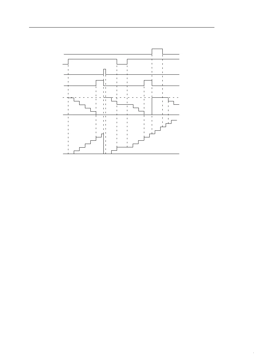
Timing diagram
Functional description
The Operating hours counter monitors input En. When En =
1, IDEC SmartRelay computes the time expired and the
time-to-go MN. IDEC SmartRelay shows these times in pa
-
rameter assignment mode. Output Q is set when the
time-to-go MN = 0.
A signal at reset input R resets output Q and sets the preset
value of MI at the counter for the duration of MN. The Oper
-
ating hours counter OT continues the count.
With a signal at the reset input Ral, you reset output Q and
set the preset value of MI at the counter for the duration of
MN. The Operating hours counter OT is reset to zero.
Depending on your configuration of parameter Q, the output
is either reset with a signal at input
R or Ral ("Q → 0:R"), or when a reset signal is set hi, or the
En signal is set lo ("Q → 0:R+En").
Par:
Q
R
Ral
En
MN=MI
OT
MN=0
MI=5h
MI = Configured time interval
MN = Time-to-go
OT = Total time expired since the last hi signal at input Ral
Courtesy of Steven Engineering, Inc. ● 230 Ryan Way, South San Francisco, CA 94080-6370 ● General Inquiries: (800) 670-4183 ● www.stevenengineering.com
 Loading...