Applications
IDEC SmartRelay Manual 272
Components used
• K1 contactor relay
• K2 contactor relay
•S0 (normally closed contact) STOP pushbutton
•S1 (normally open contact) START pushbutton
•S2 (normally open contact) flow sensor
•S3 (normally open contact) flow sensor
• H1 signal lamp
• H2 signal lamp
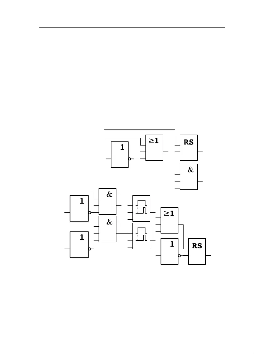
Block diagram of the IDEC SmartRelay solution
The block diagram of the air-conditioning system with IDEC
SmartRelay :
x
I1
Q3
I2
Q1
Q2
Q1
I3
x
I2
x
T=
10 s
x
T= 10 s
x
x
x
I3
I4
Q1
Q2
Q3
Exhaust
fan
On
Error
Off
Exhaust fan
Exhaust air
flow sensor
Fresh-air
flow sensor
Fresh-air fan
Exhaust fan
Exhaust air
flow sensor
Fresh-air
fan
Error
Off
Courtesy of Steven Engineering, Inc. ● 230 Ryan Way, South San Francisco, CA 94080-6370 ● General Inquiries: (800) 670-4183 ● www.stevenengineering.com
 Loading...