Programming IDEC SmartRelay
IDEC SmartRelay Manual 58
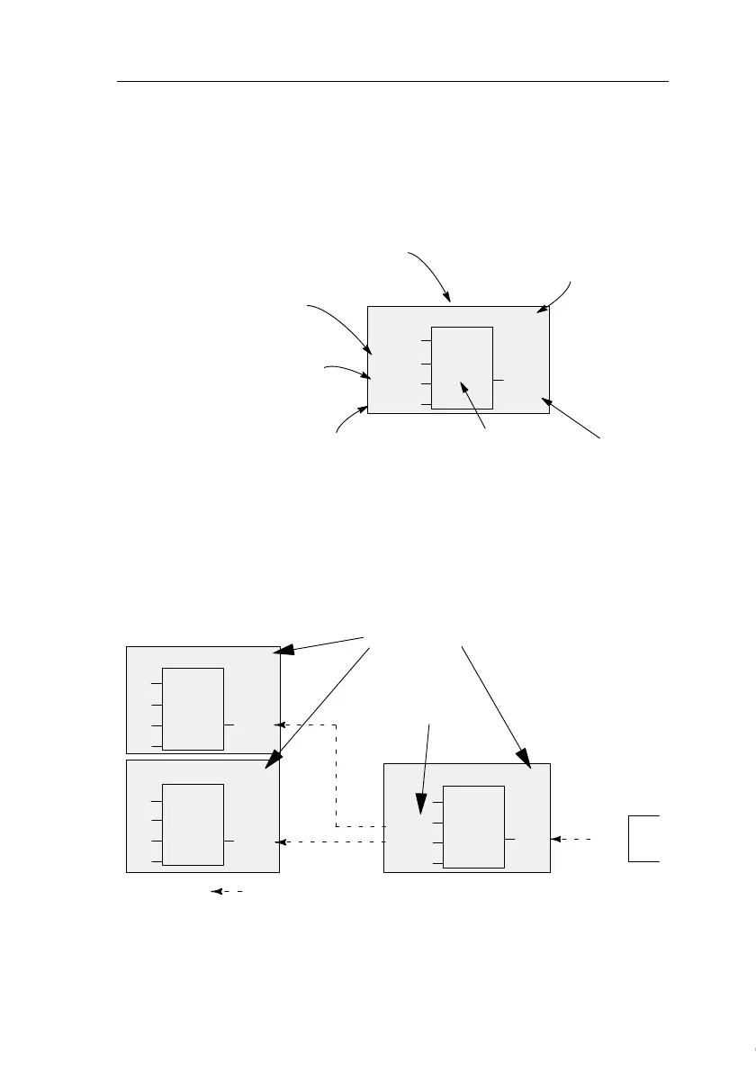
Block representation on the IDEC SmartRelay display
The figure below shows a typical view of the IDEC
SmartRelay display. As you can see, it can show only one
block at a time. We have therefore introduced block numbers
to help you check the circuit structure.
≥ 1
B2
I3
Q1
B1
x
x
View of the IDEC
SmartRelay display
A further block is
connected at this
point
Input
This connector is not required
Block
Output
Block number as-
signed by IDEC
SmartRelay
Assigning a block number
IDEC SmartRelay assigns each new block a circuit program
a block number.
IDEC SmartRelay uses these block numbers to indicate the
block interconnections. This means that these numbers are
mainly an aid to your orientation in the circuit program.
I1
I2
I3
≥ 1
B1
B2
B2
≥ 1
B3
Q1
B1
B1
I4
I5
I6
≥ 1
B1
Q1
x
B3
x
x
x
Block numbers
These blocks are
interconnected
Scrolling the circuit program using the key
▲
Courtesy of Steven Engineering, Inc. ● 230 Ryan Way, South San Francisco, CA 94080-6370 ● General Inquiries: (800) 670-4183 ● www.stevenengineering.com
 Loading...