Programming IDEC SmartRelay
IDEC SmartRelay Manual 62
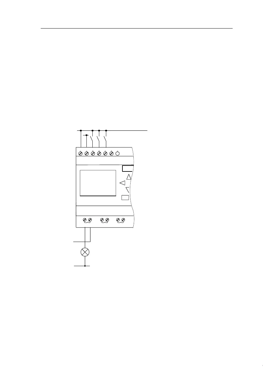
Wiring
Connect the switches S1 to S3 to the screw terminals of your
IDEC SmartRelay :
• S1 to connector I1 of IDEC SmartRelay
• S2 to connector I2 of IDEC SmartRelay
• S3 to connector I3 of IDEC SmartRelay
The output of the AND block controls the relay at output Q1.
The load E1 is connected to output Q1.
Wiring example
The following figure shows you the wiring, based on the
FL1D-H12RCC/-B12RCC.
L1
N
S
3
S
2
S
1
L1
N
NL1 I1 I2 I3 I4
1 2
Q1
Input wiring
Output wiring
Load
Courtesy of Steven Engineering, Inc. ● 230 Ryan Way, South San Francisco, CA 94080-6370 ● General Inquiries: (800) 670-4183 ● www.stevenengineering.com
 Loading...