Programming IDEC SmartRelay
83
IDEC SmartRelay Manual
What is meant by: "IDEC SmartRelay is in RUN"?
In RUN mode, IDEC SmartRelay executes the circuit pro-
gram. To do so, IDEC SmartRelay first reads the status at
the inputs, determines the status of the outputs by means of
the user program, and switches these on or off according to
your settings.
This is how IDEC SmartRelay indicates the I/O status:
Q:
0.. 123456789
1..0123456
I:
0.. 123456789
1..0123456789
2..01234
Input/output status is ‘1’:
inverted
Input/output status is ’0’:
not inverted
In this example, only the inputs I1, I15, Q8 and Q12 are set
‘high’.
Status indication on the display
I:
0.. 123456789
1..0123456789
2..01234
L1
N
S1 S2
=1
I1
I2
Q1
Q:
0.. 123456789
1..0123456
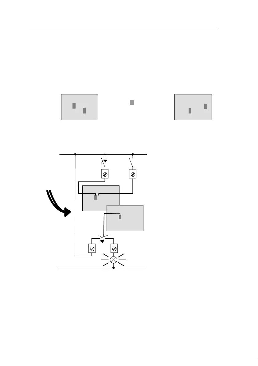
Let us examine
this, using our ex-
ample:
When switch S1 is closed,
the status at input I1 is hi.
IDEC SmartRelay computes
the output states by means
of the circuit program.
Output Q1 = ’1’, in this case.
When Q1 = ’1’, IDEC
SmartRelay sets relay Q1,
and the load connected to
Q1 is supplied with voltage.
Courtesy of Steven Engineering, Inc. ● 230 Ryan Way, South San Francisco, CA 94080-6370 ● General Inquiries: (800) 670-4183 ● www.stevenengineering.com
 Loading...