PCIE-Q57A PICMG 1.3 CPU Card
Page 16
Serial port connector (RS-232) 10-pin header COM2
SPI Flash connector 8-pin header JSPI1
USB connector (1) 8-pin header USB1
USB connector (2) 8-pin header USB2
USB connector (3) 8-pin header USB3
USB connector (4) 8-pin header USB4
Table 3-1: Peripheral Interface Connectors
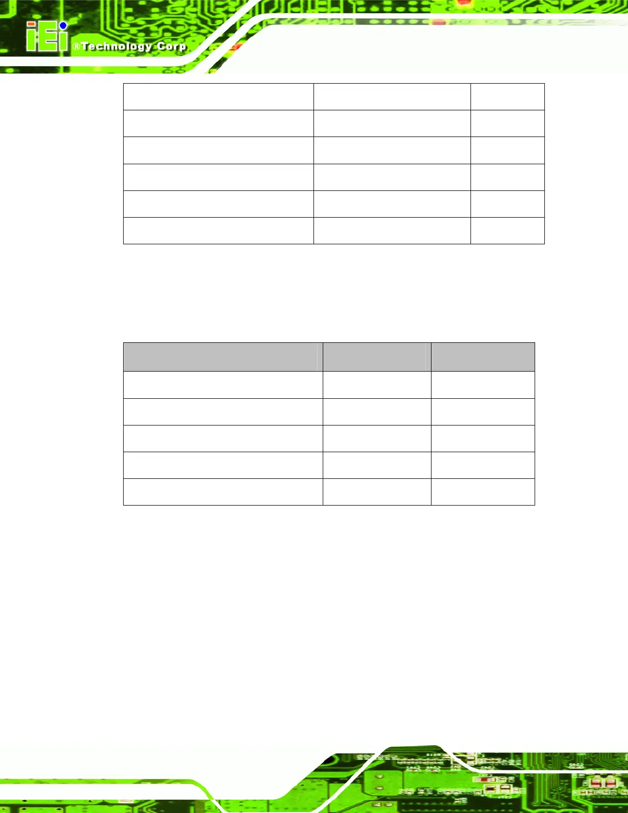
3.1.3 External Interface Panel Connectors
The table below lists the connectors on the external I/O panel.
Connector Type Label
Ethernet connector RJ-45 LAN1
Ethernet connector RJ-45 LAN2
USB port USB port USB_C1
USB port USB port USB_C2
VGA port connector 15-pin female VGA1
Table 3-2: Rear Panel Connectors
3.2 Internal Peripheral Connectors
The section describes all of the connectors on the PCIE-Q57A.
3.2.1 12V Power Connector
CN Label: CPU12V1
CN Type:
4-pin Molex power connector (1x4)
CN Location: See
Figure 3-2

 Loading...


