PCIE-Q57A PICMG 1.3 CPU Card
Page 28
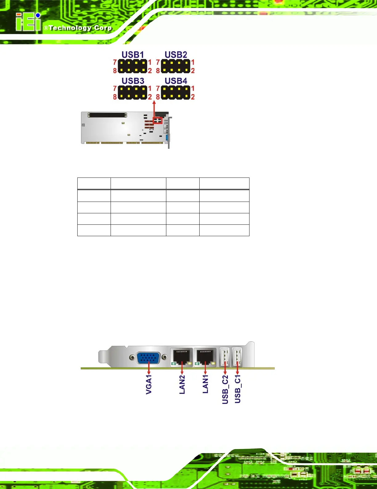
Figure 3-14: USB Connector Pinout Locations
PIN NO. DESCRIPTION PIN NO. DESCRIPTION
1 VCC 2 GND
3 DATA- 4 DATA+
5 DATA+ 6 DATA-
7 GND 8 VCC
Table 3-15: USB Port Connector Pinouts
3.3 External Peripheral Interface Connector Panel
6Figure 3-15 shows the PCIE-Q57A external peripheral interface connector (EPIC) panel.
The PCIE-Q57A EPIC panel consists of the following:
2 x Ethernet connectors
2 x USB connectors
1 x VGA connector
Figure 3-15: PCIE-Q57A External Peripheral Interface Connector

 Loading...


