PCIE-Q57A PICMG 1.3 CPU Card
Page 21
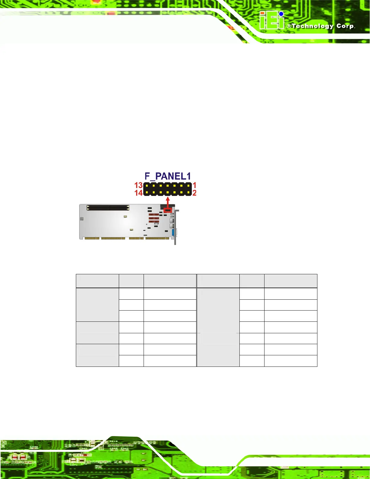
CN Location:
See
Figure 3-7
CN Pinouts:
See
Table 3-8
The front panel connector connects to external switches and indicators to monitor and
controls the motherboard. These indicators and switches include:
Power button
Reset
Power LED
HDD LED
Speaker
Figure 3-7: Front Panel Connector Location
FUNCTION PIN DESCRIPTION FUNCTION PIN DESCRIPTION
1 +5V 2 +5V
3 N/C 4 N/C
Power LED
5 GROUND 6 N/C
7 PWR_BTN+
Speaker
8 Speaker
Power Button
9 PWR_BTN- 10 N/C
11 +5V 12 RESET- HDD LED
13 HDD_LED-
Reset
14 GROUND
Table 3-8: Front Panel Connector Pinouts

 Loading...


