PCIE-Q57A PICMG 1.3 CPU Card
Page 18
PIN NO. DESCRIPTION PIN NO. DESCRIPTION
1 ACZ_SYNC 2 ACZ_BITCLK
3 ACZ_SDOUT 4 ACZ_PCBEEP
5 ACZ_SDIN 6 ACZ_RST#
7 ACZ_VCC 8 ACZ_GND
9 ACZ_12V 10 ACZ_GND
Table 3-4: Audio Connector Pinouts
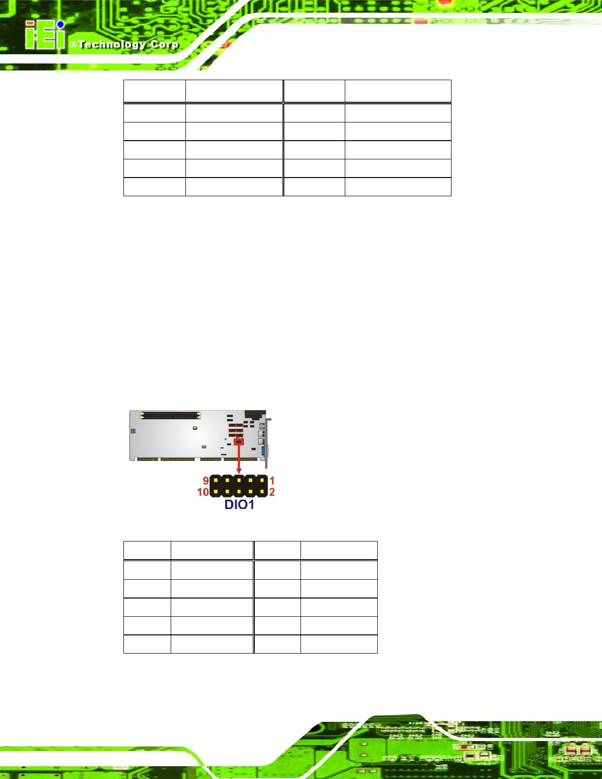
3.2.3 Digital I/O Connector
CN Label: DIO1
CN Type:
10-pin header (2x5)
CN Location:
See
Figure 3-4
CN Pinouts:
See
Table 3-5
The digital I/O connector provides programmable input and output for external devices.
The digital I/O provides 4-bit output and 4-bit input.
Figure 3-4: Digital I/O Connector Locations
Pin Description Pin Description
1 GND 2 VCC
3 Output 3 4 Output 2
5 Output 1 6 Output 0
7 Input 3 8 Input 2
9 Input 1 10 Input 0
Table 3-5: Digital I/O Connector Pinouts

 Loading...


