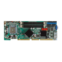
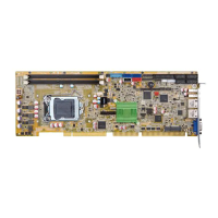
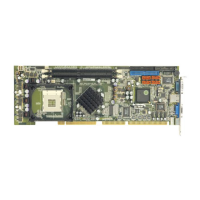
PCIE-Q57A PICMG 1.3 CPU Card
Page VIII
List of Figures
Figure 1-1: PCIE-Q57A ...................................................................................................................2
Figure 1-2: Connectors ..................................................................................................................3
Figure 1-3: PCIE-Q57A Dimensions (mm)....................................................................................4
Figure 1-4: External Interface Panel Dimensions (mm)..............................................................5
Figure 1-5: Data Flow Block Diagram...........................................................................................6
Figure 3-1: Connector and Jumper Locations...........................................................................14
Figure 3-2: CPU 12V Power Connector Location ......................................................................17
Figure 3-3: Audio Connector Location.......................................................................................17
Figure 3-4: Digital I/O Connector Locations ..............................................................................18
Figure 3-5: CPU Fan Connector Location..................................................................................19
Figure 3-6: Floppy Disk Location................................................................................................20
Figure 3-7: Front Panel Connector Location .............................................................................21
Figure 3-8: Infrared Connector Location....................................................................................22
Figure 3-9: Keyboard/Mouse Connector Location....................................................................23
Figure 3-10: Parallel Port Connector Location..........................................................................24
Figure 3-11: SATA Drive Connector Locations .........................................................................25
Figure 3-12: COM Connector Pinout Locations ........................................................................26
Figure 3-13: SPI Flash Connector...............................................................................................27
Figure 3-14: USB Connector Pinout Locations .........................................................................28
Figure 3-15: PCIE-Q57A External Peripheral Interface Connector..........................................28
Figure 3-16: RJ-45 Ethernet Connector......................................................................................29
Figure 3-17: VGA Connector .......................................................................................................30
Figure 4-1: Disengage the CPU Socket Load Lever..................................................................37
Figure 4-2: Remove Protective Cover.........................................................................................37
Figure 4-3: Insert the Socket LGA1156 CPU..............................................................................38
Figure 4-4: Close the Socket LGA1156 ......................................................................................39
Figure 4-5: Cooling Kit Support Bracket....................................................................................40
Figure 4-6: DIMM Installation.......................................................................................................41
Figure 4-7: Jumper Locations .....................................................................................................42
Figure 4-8: Clear CMOS Jumper .................................................................................................43
Figure 4-9: Dual RS-232 Cable Installation ................................................................................45
 Loading...
