ESD capability IEC 61000-4-2 (ESD) ± 15 kV (air), ± 8 kV (contact)
Input current 2 mA @ 5 V; 5 mA @ 15V
High level differential input voltage (HS_GPI2+ - HS_GPI2-) > 150 mV
Low level differential input voltage (HS_GPI2+ - HS_GPI2-) < -600 mV
Recommended PWM signal for single ended 1.2 V to 24 V (HS_GPI2- connected to GND).
pk pk
Ready for 3.3 V and 5 V logic.
Recommended frequency range 500 Hz to 20 kHz
Maximum frequency range 250 Hz to 50 kHz
Minimum detectable pulse width 200 ns
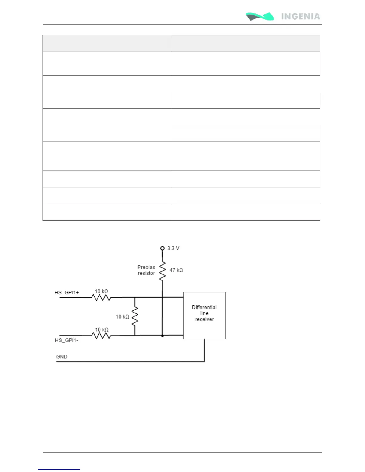
Next Figure shows the circuit model for the PWM encoder input. The PWM input can work perfectly with 5
V or 3.3 V logic signals. Just connect the negative input to GND.
PWM encoder modes
There are two different working modes for this command source:
Single input mode
In this mode, only one input signal is used. PWM command is a PWM signal whose duty cycle sets the
target position, velocity or torque.
For velocity mode, a duty cycle of 50% corresponds with 0 rpm. A 0% duty cycle corresponds with the
maximum velocity in one direction, and a 100% duty corresponds to the maximum velocity in the opposite
direction. Position and torque modes work in a similar way.