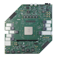
Figure 24. Cypress and Micron M28, M29 Flash Memory in 8-Bit Mode
The flash memory addresses in Cypress 8-bit flash shifts one bit up. Address bit 0 of the PFL II IP core connects to data pin D15 of the flash memory.
23
22
21
-
-
-
2
1
0
address: 24 bits
22
21
20
-
-
-
1
0
D15
address: 24 bits
PFL II
Flash Memory
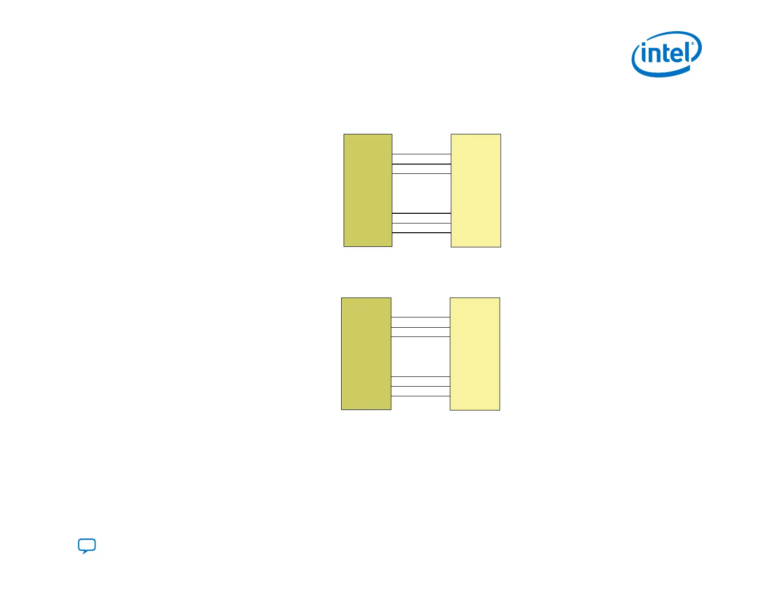
Figure 25. Cypress and Micron M28, M29 Flash Memory in 16-Bit Mode
The address bit numbers in the PFL II IP core and the flash memory device are the same.
22
21
20
-
-
-
2
1
0
address: 23 bits
22
21
20
-
-
-
2
1
0
address: 23 bits
PFL II Flash Memory
3.1.10.1.4. Implementing Multiple Pages in the Flash .pof
The PFL II IP core stores configuration data in a maximum of eight pages in a flash memory block.
3. Intel Agilex Configuration Schemes
UG-20205 | 2019.10.09
Send Feedback
Intel
®
Agilex
™
Configuration User Guide
63