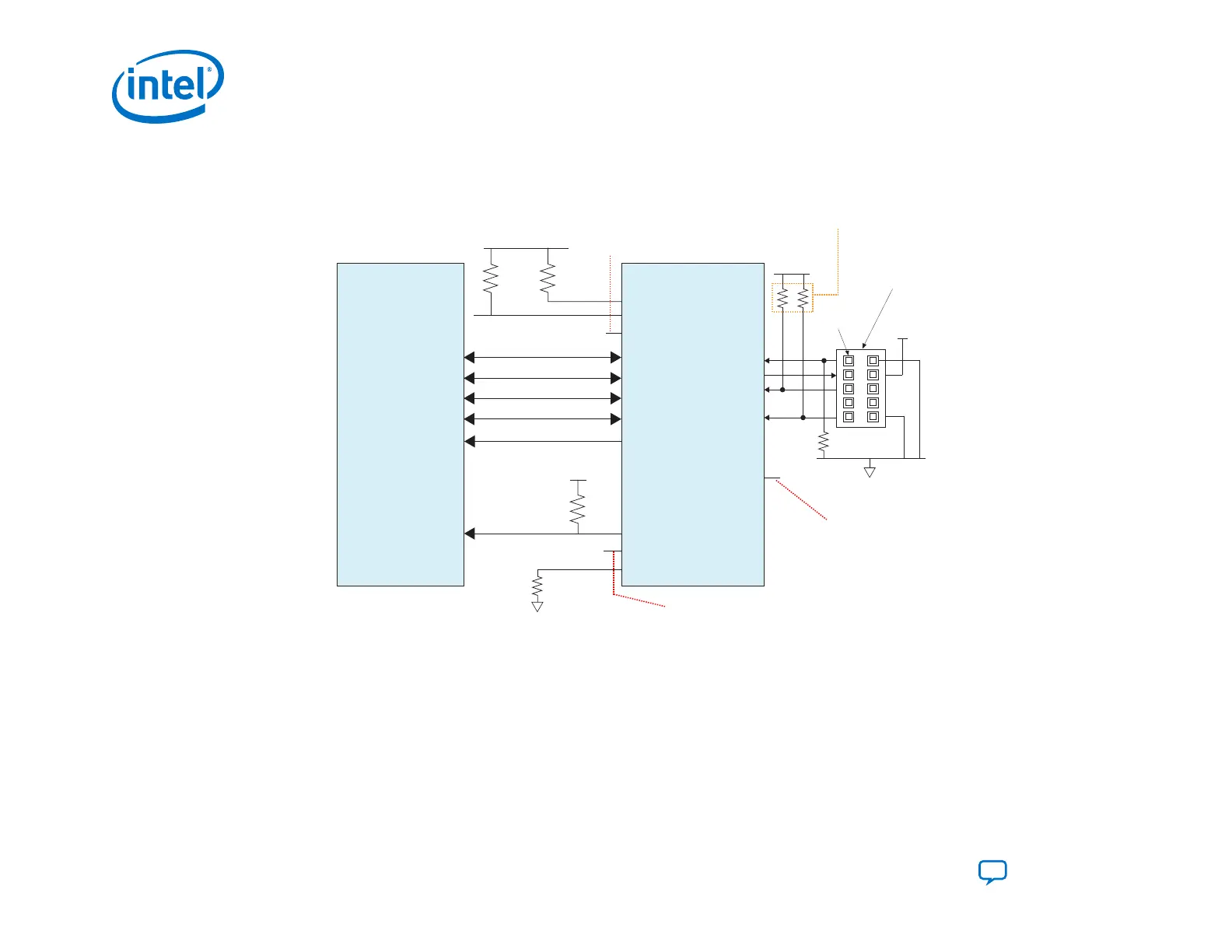
Figure 41. Connections for Programming the Serial Flash Devices using the JTAG Interface
Download Cable
10-Pin Male Header
(JTAG Mode) (Top View)
TDI
TMS
TDO
TCK
Pin 1
1 kΩ
Resistor values can vary between 1 kΩ to 10 kΩ.
Perform signal integrity analysis to select
the resistor value for your setup.
AS_DATA[0]
AS x4 Flash Device
Intel FPGA
nSTATUS
nCONFIG
CONF_DONE
OSC_CLK_1
DATA0
DATA1
DATA2
DATA3
DCLK
nCS
AS_DATA[1]
AS_DATA[2]
AS_DATA[3]
AS_CLK
4.7 kΩ
GND
GND
V
CCIO_SDM
V
CCIO_SDM
10 kΩ
V
CCIO_SDM
10 kΩ
4.7 kΩ
V
CCIO_SDM
MSEL [0]/AS_nCSO[0]
MSEL [1]
MSEL [2]
AS fast mode: Pull MSEL [1] low using 4.7 kΩ resistor
AS normal mode: Pull MSEL [1] high using 4.7 kΩ resistor
External clock source to feed
the is optional.
For external ref clk, OSC_CLK_1
is required.
CONF_DONE connection
to external host for
monitoring is optional.
3M Part number : 2510-6002UB
3. Intel Agilex Configuration Schemes