11
4 Layout of components and componentry
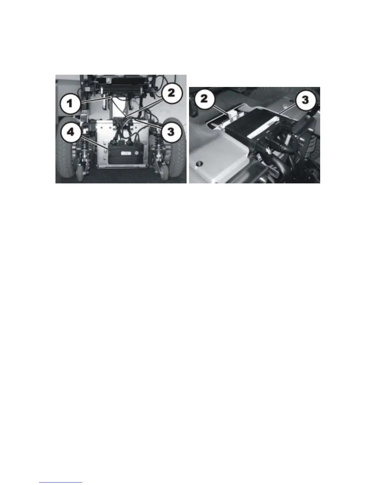
4.1 Overview
The electronic control modules and regulators are situated at the rear underneath the rear plastic
cover and directly under the seat.
Directly under the seat:
• Actuator module (1)
The actuator module is optional. If available, it controls the electric leg supports, the electric tilt
module and the electric back adjustment.
Underneath the rear cover:
• Light terminal block (2)
The light terminal block is in front of the actuator module (3). The light terminal block is
optional. It is only available if the mobility aid is fitted with lighting.
• Actuator module (3)
The actuator module is on the top of the battery compartment. The actuator module is
optional. It is only available if the mobility aid is fitted with a lifter.
• Power module (4)
The power module is at the rear of the battery compartment.