67
8.4.5 Replacing the lighting PCB
Replacement is described in the following section based on the example of a mobility aid with an
optional lighting PCB and an optional actuator module.
Requirements:
• 4 mm Allen key
• 8 mm socket spanner
Dismantling the lighting PCB:
• If possible, use the lifter to move the seat to the uppermost position.
• Remove the rear and the centre cover as described in chapters 8.1.1 and Fehler!
Verweisquelle konnte nicht gefunden werden..
• Carefully note the location of the cable and the connection locations of the various plugs.
Either mark each plug and socket, or take a photograph with a digital camera.
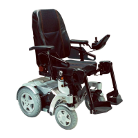
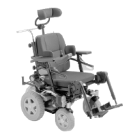
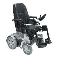
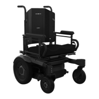
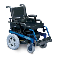
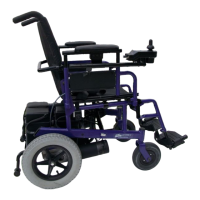
• The pictures show the power module (4), the optional lighting PCB (2) and the optional
actuator modules (1) & (3).
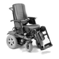
• Pull the plug (1) out of the lighting PCB.
• Undo the two Allen screws (2) with a 4 mm Allen key.
• Lift off the lighting PCB together with the retaining bracket.