Goodrive270 series VFD for fan and pump Basic operation guidelines
-72-
Function
Name Description Default
P12.20
Stator resistance of SM
0.001±ȍ
Model
P12.21
Direct-
0.01±655.35mH
Model
P12.22
Quadrature-axis
0.01±655.35mH
Model
P12.23 Counter-
0±10000 300
5.5.7 Start/stop control
The start/stop control of the VFD involves three states: start after a running command is given at
power-on; start after power-off restart is effective; start after automatic fault reset. The three start/stop
control states are described in the following.
There are three start modes for the VFD, which are start at starting frequency, start after DC braking,
and start after speed tracking. You can select the proper start mode based on actual conditions.
For large-inertia load, especially in cases where reversal may occur, you can choose to start after DC
braking or start after speed tracking.
Note: It is recommended to drive SMs in direct start mode.
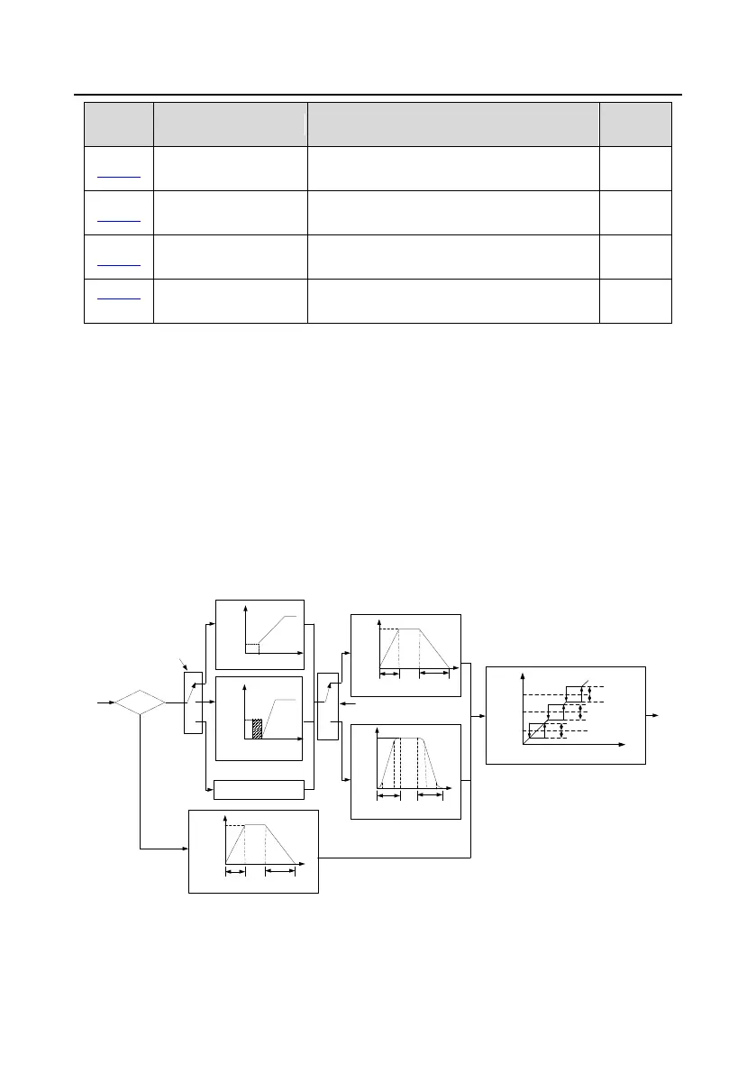
1. Logic diagram for start after a running command is given at power-on
Jogging?
N
1f
1t
P00.11
Acceleration
time
P00.12
Deceleration time
Acceleration
process
Deceleration
process
P00.03
Acceleration
process
Deceleration
process
P00.03
1f
1t
P08.07
Acceleration
time
P08.08
Deceleration time
Acceleration
process
Deceleration
process
P08.06
1t
1f
1t
Jump
frequency 2
1/2* jump amplitude 2
1/2* jump amplitude 2
Jump
frequency 1
1/2* jump amplitude 1
1/2* jump amplitude 1
Jump
frequency 3
1/2* jump amplitude 3
1/2* jump amplitude 3
Y
Start after speed-tracking
P01.00
Running mode of start
Starting
frequency of
direct start
Hold time of starting frequency
Brake time before
start
Brake
current
before start
P01.05
Acceleration/deceleration mode
selection
P00.11
Acceleration
time
P00.12
Deceleration time
0
1
2
0
1
Straight-type
acceleration/deceleration
S curve-type
acceleration/deceleration
Direct start
Start after DC brake
Running
frequency of
jogging
1f
2. Logic diagram for start after power-off restart is effective
 Loading...