Goodrive270 series VFD for fan and pump Basic operation guidelines
-115-
received after the protection has been activated, the motor is stopped and automatic protection is
disabled. Automatic protection can be enabled only when the temperature is higher than the
protection threshold.
5.5.18 Electric wiring and timing diagram of HVAC function
The value 0 of P94.10 indicates using the fixed variable-frequency pump logic. When
variable-frequency motors are fixed, only power-frequency pumps can be switched over.
The value 1 of P94.10 indicates using the cyclic variable-frequency pump logic. Then four relays can
be used to control the variable/power frequency switchover of four motors
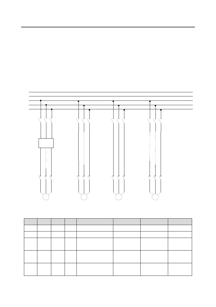
5.5.18.1 Main circuit wiring diagram of one driving four in fixed variable-frequency pump logic
PE
N
L1
L2
L3
VFD
M1 M2 M3 M4
QF1 QF2
QF3 QF4 QF5
KM1 KM2 KM3 KM4
R S T
U V W
Figure 5±6 Control circuit wiring diagram in fixed variable-frequency pump logic
Table 5-2 Motor adding logic with fixed variable-frequency motors
1 1 0 0 Variable frequency
Power
Stop Stop
1 1 1 0 Variable frequency
Power
Power
Stop
1 1 1 1 Variable frequency
Power
Power
Power
 Loading...