Goodrive270 series VFD for fan and pump Basic operation guidelines
-82-
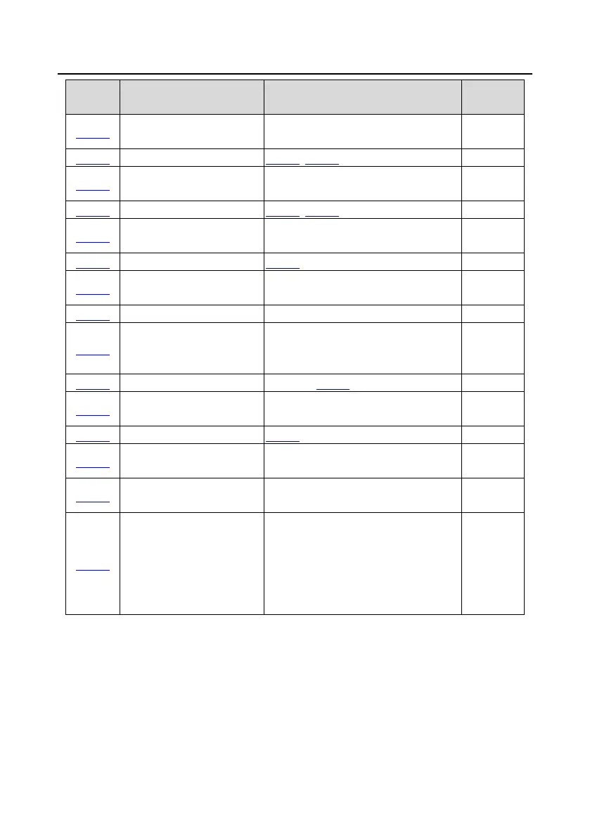
Function
Name Description Default
P05.30
Corresponding setting of AI2
-300.0%±300.0% -100.0%
P05.32
Corresponding setting of AI2
-300.0%±300.0% 0.0%
P05.34
Corresponding setting of AI2
-300.0%±300.0% 0.0%
P05.36
Corresponding setting of AI2
-300.0%±300.0% 100.0%
P05.38
HDIA high-speed pulse input
function selection
0: Frequency setting
1: Reserved
0
HDIA lower limit frequency
P05.40
Corresponding setting of
HDIA lower limit frequency
-300.0%±300.0%
0.0%
HDIA upper limit frequency
P05.42
Corresponding setting of
HDIA upper limit frequency
-300.0%±300.0%
100.0%
P05.43
HDIA frequency input filter
0.000s±10.000s
0.030s
P05.50 AI1 input signal type
0±1
0: Voltage
1: Current
Note: If
the input type is current, the
AI-
I short cap on the control board
needs to be shorted.
0
5.5.10 Analog output
The VFD carries two analog output terminals (0±10V/0±20mA) and one high-speed pulse output
terminal. Analog output signals can be filtered separately, and the proportional relation can be
adjusted by setting the max. value, min. value, and the percentage of their corresponding output.
Analog output signal can output motor speed, output frequency, output current, motor torque and
motor power at a certain proportion.
 Loading...