Goodrive270 series VFD for fan and pump Technical data
-305-
B.2.2.3 Derating due to carrier frequency
The carrier frequency of the VFD varies with power class. The VFD rated power is defined based on
the carrier frequency factory setting. If the carrier frequency exceeds the factory setting, the VFD
power is derated by 10% for each increased 1 kHz.
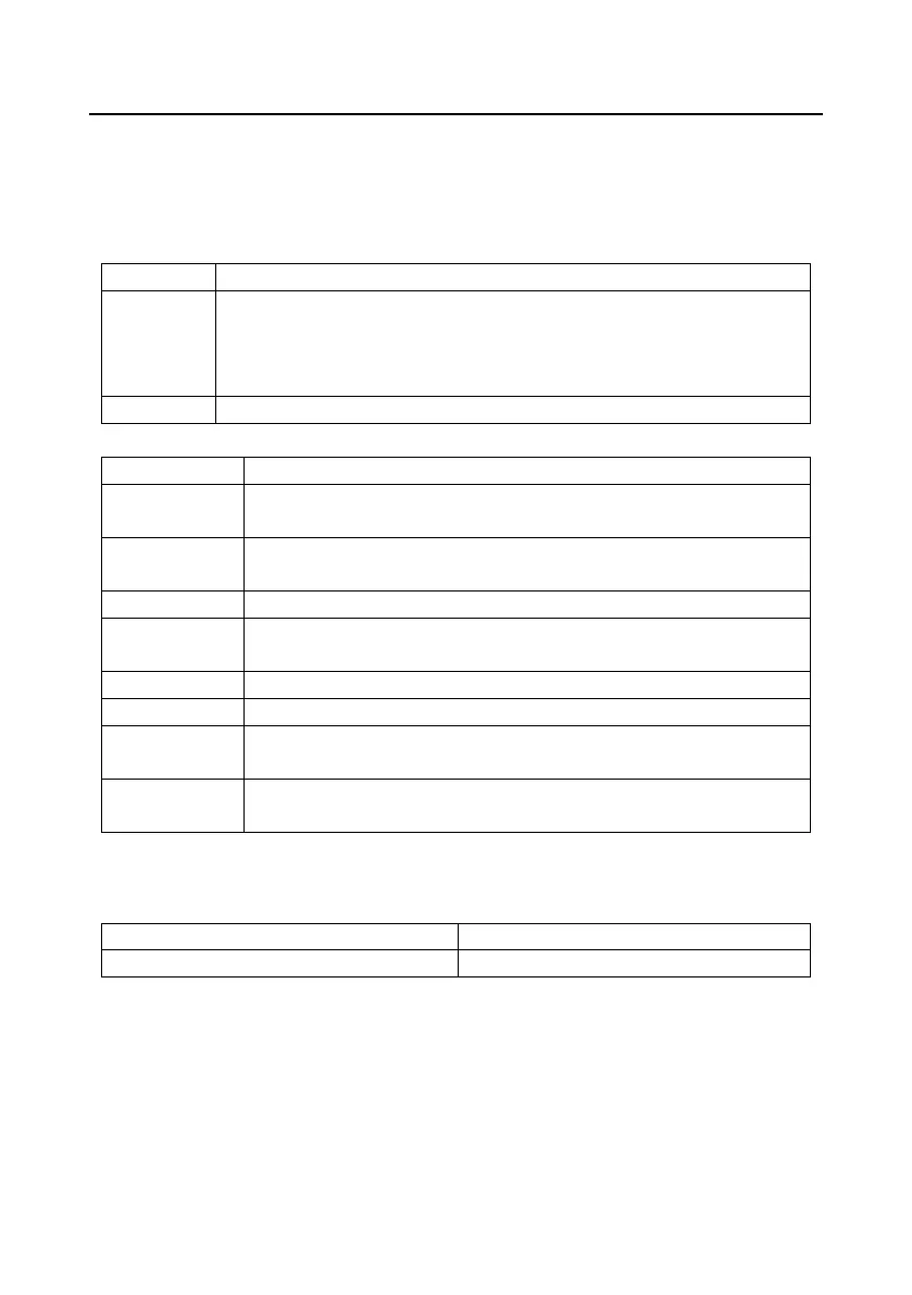
B.3 Grid specifications
Short-circuit
capacity
According to the definition in IEC 60439-1, the maximum allowable short-circuit
current at the incoming end is 100 kA. Therefore, the VFD is applicable to
scenarios where the transmitted current in the circuit is no larger than 100 kA
when the VFD runs at the maximum rated voltage.
50/60 Hz±5%, with a maximum change rate of 20%/s
B.4 Motor connection data
Asynchronous induction motor or permanent-magnet synchronous motor
Voltage
0±U1 (motor rated voltage), 3PH symmetrical, Umax (VFD rated voltage) at
the field-weakening point
Short-circuit
The motor output short-circuit protection meets the requirements of IEC
Frequency
0.01 Hz
See section 3.6 Product ratings.
1.1 times of the rated power of the motor
Field-weakening
10...400 Hz
Carrier
2, 4, 8, 12, or 15 kHz
B.4.1 EMC compatibility and motor cable length
The following table describes the maximum motor cable lengths that meet the requirements of the EU
EMC directive (2014/30/EU).
All models (with external EMC filters)
Maximum motor cable length (m)
Environment category II (C3)
You can learn the maximum length of the motor cable through the running parameters of the VFD. To
understand the accurate maximum cable length for using an external EMC filter, contact the local
INVT office.
For details about the environment categories, see section B.6 EMC regulations.
B.5 Application standards
The following table describes the standards that VFDs comply with.
 Loading...