Goodrive270 series VFD for fan and pump Expansion card
-299-
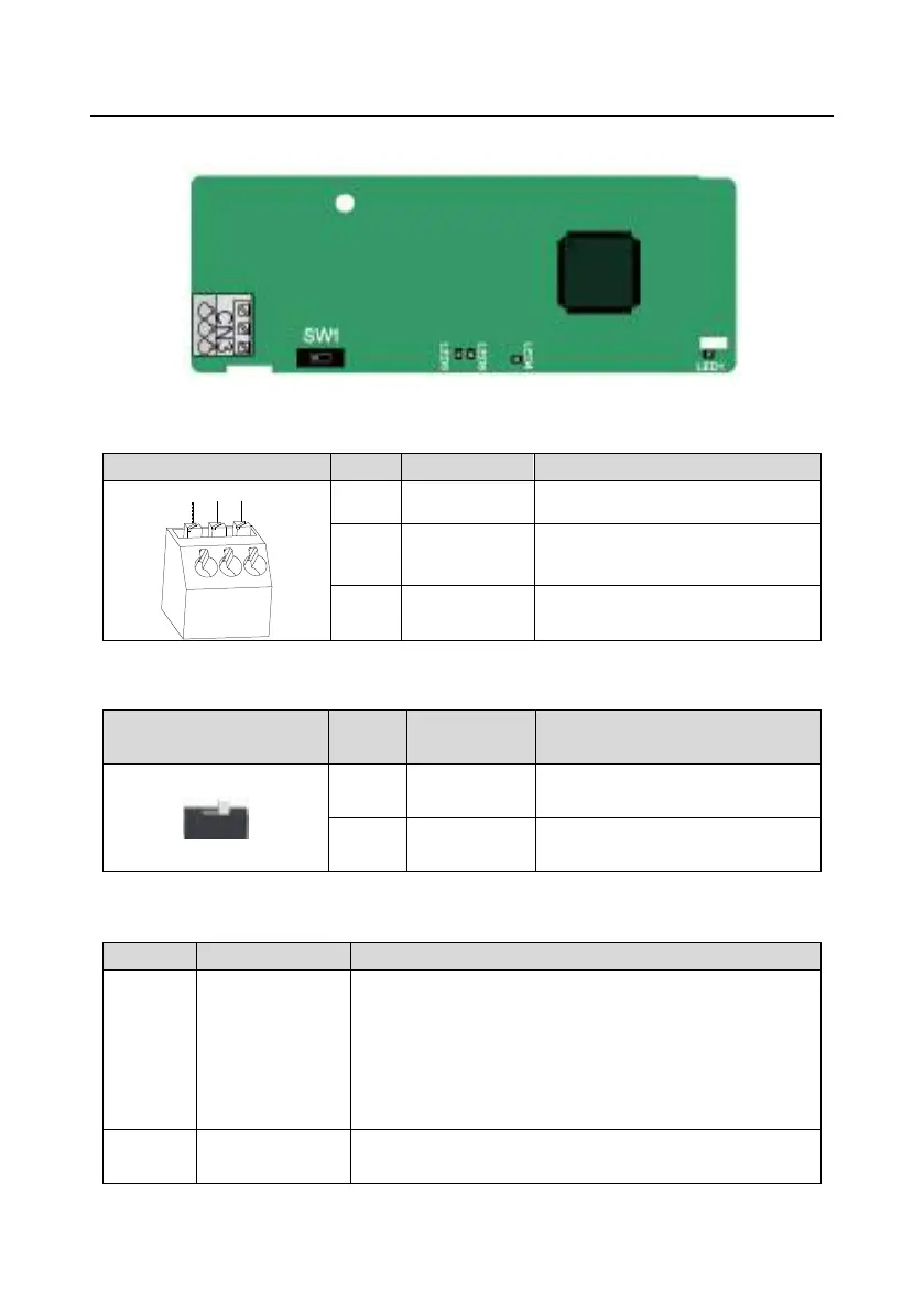
A.5.3 CANopen communication card (EC-TX511) and CAN master/slave control
communication card (EC-TX511)
The EC-TX505/511 communication card is user-friendly, adopting spring terminals.
1 CANH CANopen bus high level signal
2 CANG CANopen bus shielding
3 CANL CANopen bus low level signal
Terminal resistor switch function description:
Terminal resistor switch
Position
Function Description
Left OFF
CAN_H and CAN_L are not
connected to a terminal resistor.
Right ON
CAN_H and CAN_L are connected to
DWHUPLQDOUHVLVWRURIȍ
Indicator definition:
LED1 Status indicator
This indicator is on when the expansion card is establishing a
connection with the control board;
it blinks periodically after the expansion card is properly
connected to the control board (the period is 1s, on for 0.5s,
and off for the other 0.5s) and it is off when the expansion
card is disconnected from the control board.
LED4 Power indicator
This indicator is on after the control board feeds power to the
 Loading...