Goodrive270 series VFD for fan and pump Expansion card
-302-
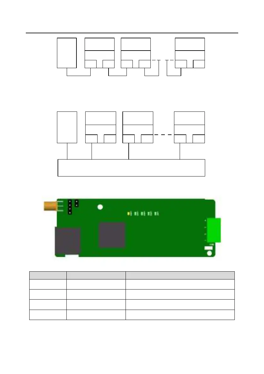
Master
device
Slave device 2
RJ45
RJ45
Slave device 1
RJ45
RJ45
Slave device n
RJ45
RJ45
Figure A±5 Linear network topology electrical connection diagram
Note: For the star network topology, you need to prepare PROFINET switches.
The star network topology electrical connection diagram is shown in Figure A±6.
Master
device
Slave device 2
RJ45
RJ45
Slave device 1
RJ45
RJ45
Slave device n
RJ45
RJ45
Switch
Figure A±6 Star network topology electrical connection diagram
A.5.5 GPRS IoT card²EC-IC501-2
CN6 pins are defined as follows.
Indicator definition:
The GPRS IoT card has five status indicators.
 Loading...