Goodrive270 series VFD for fan and pump Product overview
-7-
3 Product overview
3.1 What this chapter contains
This chapter mainly introduces the working principles, product features, layouts, nameplates and
model designation rules.
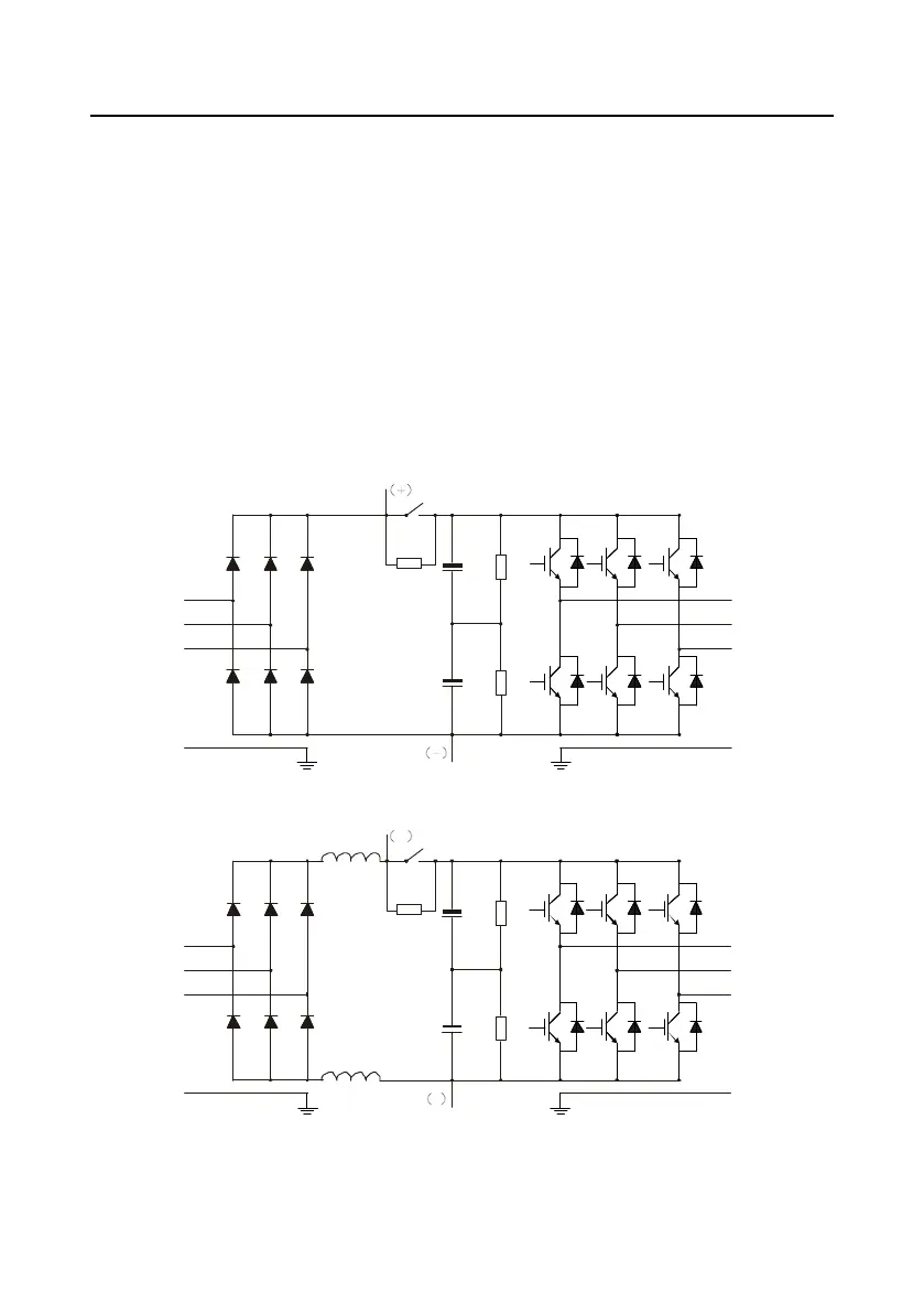
3.2 Basic principles
The VFD is used to control asynchronous AC induction motors and permanent magnetic synchronous
motors. The following figure shows the main circuit diagram of the VFD. The rectifier converts 3PH
AC voltage into DC voltage, the capacitor bank of intermediate circuit stabilizes the DC voltage, and
then the inverter converts DC voltage into AC voltage that can be used by an AC motor. When the
circuit voltage exceeds the maximum limit value, external braking resistor will be connected to
intermediate DC circuit to consume the feedback energy.
Figure 3-1 Simplified main circuit diagram
R
S
T
U
V
W
˄
+˅
˄-˅
Optional DC
reactor
PE PE
Figure 3±2 Main circuit diagram for 400±500kW (included) models (with built-in DC reactors)
Note: No DC reactors have been built in standard models.
 Loading...