Goodrive270 series VFD for fan and pump Dimension drawings
-308-
Appendix C Dimension drawings
C.1 What this chapter contains
This chapter provides the dimension drawings of the VFD. which uses millimeter (mm) as the unit.
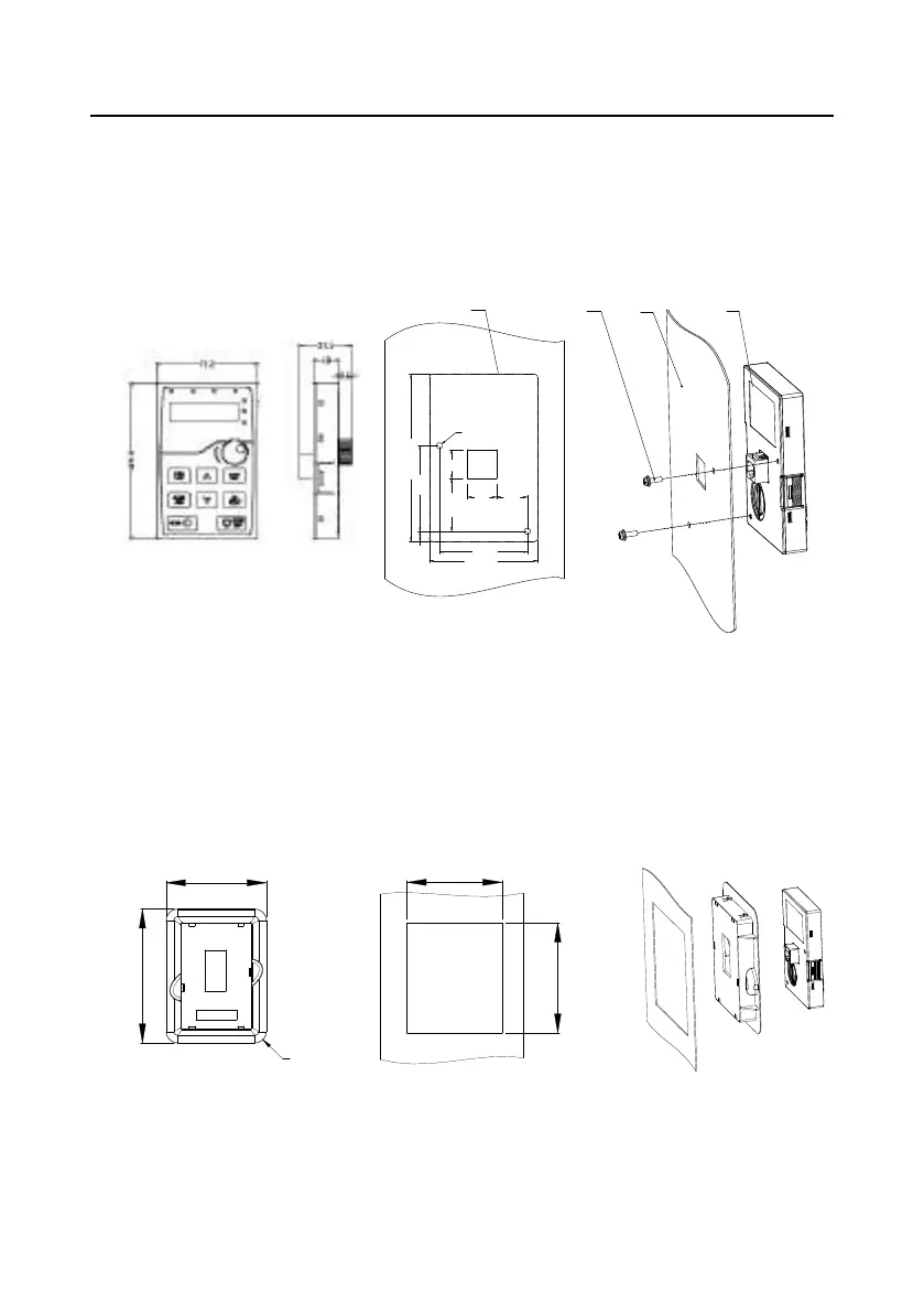
C.2 Keypad structure
C.2.1 Structure diagram
Installation hole dimensions and diagram for key installation without bracket
Outer outline of the keypad
2-
M
3
×10
assembled screw
Panel
Keypad
109.3
56
6.7
71.3
58
2- ø4
1934.4
19
20.4
Figure C-1 Keypad structure
C.2.2 Keypad mounting bracket
Note: The external keypad can be mounted directly with M3 threaded screws or with a keypad
bracket. For 380V 30±90kW VFD models, the keypad mounting bracket is an optional part. For
380V 110±500kW VFD models, you can use optional brackets or use the standard keypad
brackets externally.
Installation dimensionsKeypad adapter bracket
103
98
140
115
4-R12
Figure C±2 Keypad mounting bracket (Optional)
 Loading...