Goodrive270 series VFD for fan and pump Communication
-269-
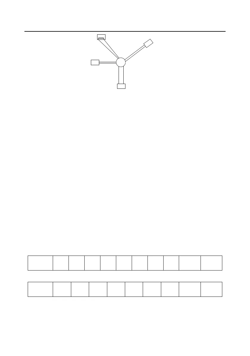
1#
15#
32#
6
#
Main control
device
Figure 9±5 Star connection
Use shielded cables, if possible, in multi-device connection. The baud rates, data bit check settings,
and other basic parameters of all the devices on the RS485 line must be set consistently, and
addresses cannot be repeated.
9.3.2 RTU mode
9.3.2.1 RTU communication frame structure
When a controller is set to use the RTU communication mode on a Modbus network, every byte (8
bits) in the message includes 2 hexadecimal characters (each includes 4 bits). Compared with the
ASCII mode, the RTU mode can transmit more data with the same baud rate.
Code system
VWDUWELW
RUGDWDELWVWKHPLQLPXPYDOLGELWLVWUDQVPLWWHGILUVW (DFKIUDPHGRPDLQRIELWVLQFOXGHV
hexadecimal characters (0±9, A±F).
RGGHYHQFKHFNELWWKLs bit is not provided if no check is needed.
HQGELWZLWKFKHFNSHUIRUPHGELWVZLWKRXWFKHFN
Error detection domain
&\FOLFUHGXQGDQF\FKHFN&5&
The following table describes the data format.
11-bit character frame (Bits 1 to 8 are data bits)
Start bit BIT1 BIT2 BIT3 BIT4 BIT5 BIT6 BIT7 BIT8
Check
Stop
10-bit character frame (Bits 1 to 7 are data bits)
Start bit BIT1 BIT2 BIT3 BIT4 BIT5 BIT6 BIT7
Check
Stop
In a character frame, only the data bits carry information. The start bit, check bit, and end bit are used
to facilitate the transmission of the data bits to the destination device. In practical applications, you
must set the data bits, parity check bits, and stop bits consistently.
 Loading...