Goodrive270 series VFD for fan and pump Installation guidelines
-35-
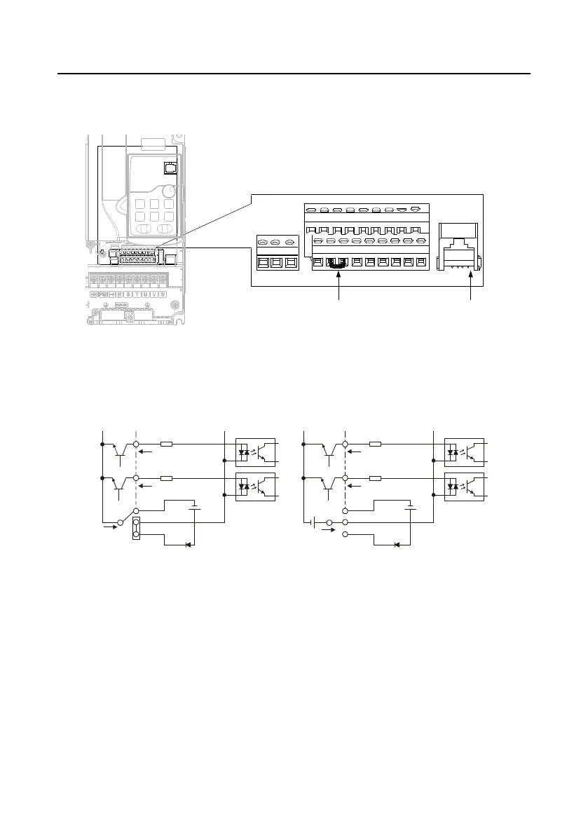
4.4.2 Input/output signal connection diagram
Set NPN /PNP mode and internal/external power via U-type short-contact tag. NPN internal mode is
adopted by default.
U-type short-contact tag
between +24V and PW
Keypad
interface
+24V 485+ 485-
AO0
R01A R01B
PW COM
AO1
GND
S1 S2 S3
S4/Y1
HDIA
AI1 AI2 +10V
R01C
PE COM
Figure 4±30 Position of U-type short-contact tag
Note: The keypad interface can be used to connect an external keypad, but the external
keypad cannot be used when the local VFD keypad is used.
If the input signal comes from the NPN transistor, set the U-type short-contact tag between +24V and
PW based on the power used according to the following figure.
S1
S2
COM
PW
+
24V
COM
+ 24V
Internal powerNPN mode
S1
S2
COM
PW
+ 24V
COM
+
24V
External powerNPN mode
+ 24V
Figure 4±31 NPN mode
If the input signal comes from the PNP transistor, set the U-type short-contact tag based on the power
used according to Figure 4±32.
 Loading...