Goodrive270 series VFD for fan and pump Installation guidelines
-32-
R, S, T 3PH AC input terminals, connecting to the grid
U, V, W 3PH AC output terminals, which connect to the motor in most cases
(+) and (-) connect to the external braking unit terminals or the shared
DC bus.
(+) connects to the external braking resistor terminal.
(-)
PE
Grounding terminal for safe protection; each machine must carry two PE
terminals and proper grounding is required
Note:
Do not use asymmetrical motor cables. If there is a symmetrical grounding conductor in the motor
cable besides the conductive shielded layer, ground the grounding conductor on the VFD end
and motor end.
Route the motor cable, input power cable and control cable separately.
(+) and (-) are only used for multiple VFDs sharing the DC bus but not used for DC power input.
4.3.3 Wiring procedure for main circuit terminals
1. Connect the grounding line of the input power cable to the grounding terminal (PE) of the VFD,
and connect the 3PH input cable to R, S and T terminals and tighten up.
2. Connect the ground wire of the motor cable to the PE terminal of the VFD, connect the motor 3PH
cable to the U, V and W terminals, and tighten up.
3. Connect optional parts such as the braking resistor that carries cables to designated positions.
4. Fasten all the cables outside the VFD mechanically if allowed.
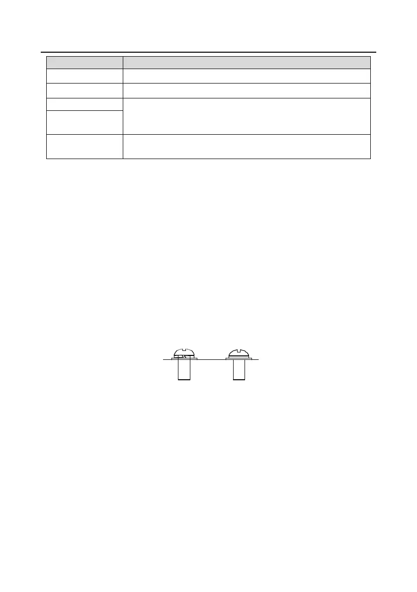
The screw is
not fastened.
The screw is
fastened.
YNG
Figure 4±28 Screw installation diagram
 Loading...