Goodrive270 series VFD for fan and pump Basic operation guidelines
-38-
5 Basic operation guidelines
5.1 What this chapter contains
This chapter instructs you how to use the VFD keypad and commission the VFD common functions.
5.2 Keypad introduction
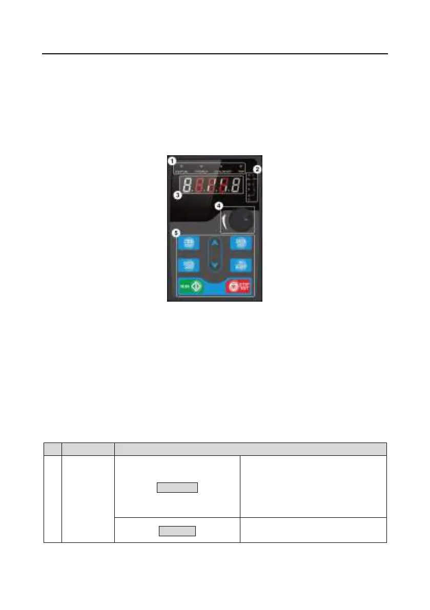
The VFD has been equipped with a LED keypad as a standard configuration part. You can use the
keypad to control the start and stop, read status data, and set parameters of the VFD.
Figure 5±1 Keypad
Note:
The LED keypad is a standard part for the VFD. In addition, the LCD keypad (an optional part)
can be provided as required. The LCD keypad supports multiple languages, parameter copying
function, and ten-row high-definition display. The installation size of the LCD is compatible with
the LED keypad.
If you need install the keypad externally (that is, on another position rather than on the VFD), you
can use M3 screws to fix the keypad, or you can use the keypad installation bracket to install the
keypad. The installation bracket is an optional part for 380V 1.5±30kW, but it is a standard part
for 380V 37±500kW.
1
Status
indicator
RUN/TUNE
VFD running status indicator.
Off: The VFD is stopped.
Blinking: The VFD is autotuning
parameters.
FWD/REV
Forward or reverse running indicator.
LED off: The VFD is running forward.
 Loading...