Goodrive270 series VFD for fan and pump Installation guidelines
-33-
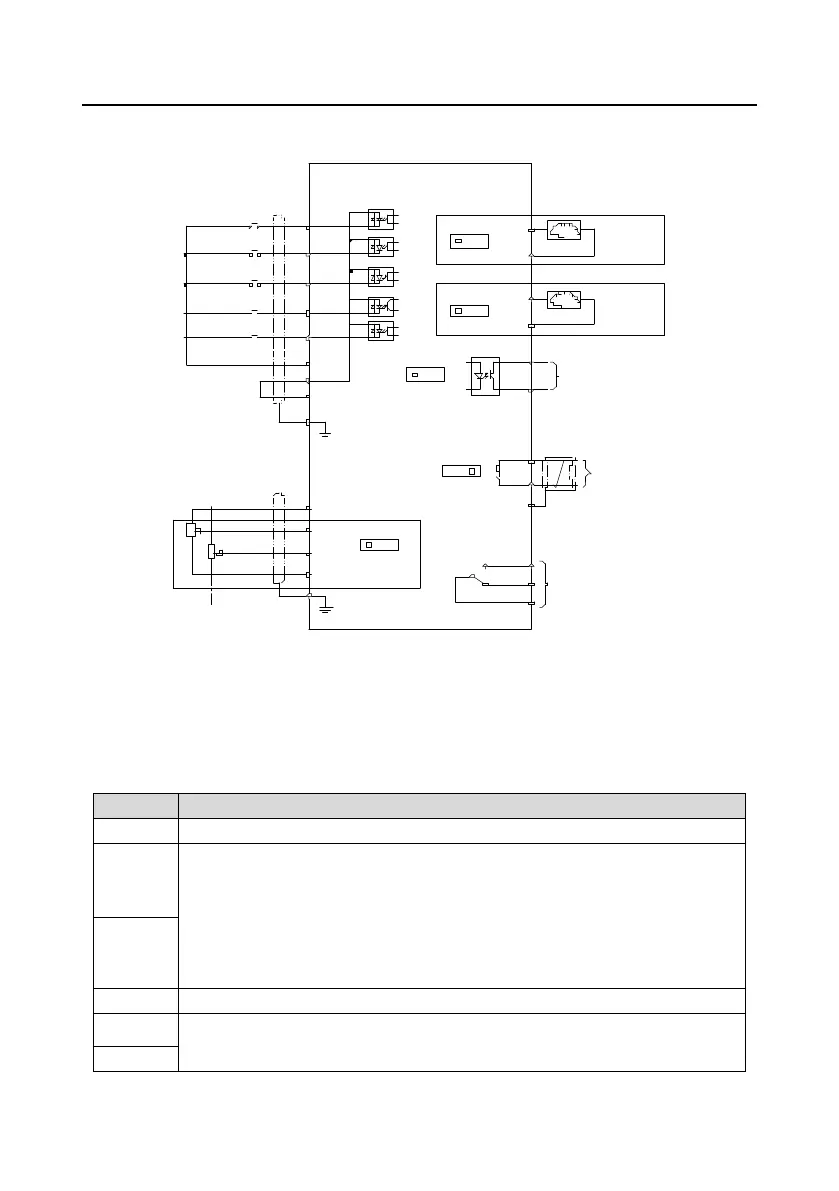
4.4 Standard wiring of the control circuit
4.4.1 Wiring diagram of basic control circuit
+24V
PE
COM
S4
S3
S2
S1
PW
HDIA
FWD run
FWD jog
Fault reset
+10V
AI1
AI2
GND
PE
-10V
(External)
VFD
AO0
V I
J7
GND
Analog output
0-10V/0-20mA
S4/Y1
COM
485+
485-
485G
RS485
communication
RO1C
RO1B
RO1A
Relay 1
output
ON
OFF
J8
Multifunction analog input
Power used for
frequency setting
Y1
output
AO1
V I
J6
GND
Analog output
0-10V/0-20mA
V I
J11
S4 Y1
J10
Figure 4±29 Control circuit wiring diagram
Note: If wire-passing board outlet space is insufficient when all terminals on the control board
are wired, cut the knock-out hole on the lower cover for wire outlet. If a dangerous situation
occurs when the knock-out hole is cut for a purpose but not wire outlet, we will not bear any
responsibility.
Locally provided +10.5V power supply
AI1
Input range: For AI1, 0(2)±10V or 0(4)±20mA
For AI2, -10V±+10V
,QSXWLPSHGDQFHNȍIRUYROWDJHLQSXWȍIRUFXUUHQWLQSXW
Whether voltage or current is used for input is set through jumper J11.
Resolution: 5mV when 10V corresponds to 50Hz
Deviation: ±0.5% at 25°C, when input is above 5V/10mA
AI2
Reference zero potential of +10.5V
AO0
Output range: 0(2)±10V or 0(4)±20mA
Whether voltage or current is used for output of AO0 and AO1 is set through
 Loading...