Goodrive300-LIFT series inverter Function parameters
-40-
Detailed instruction of parameters
braking, the inverter will close output and begin
to carry on the DC braking after the waiting time.
This function avoids the overcurrent fault caused
by DC braking when the speed is too high.
Stop DC braking current: DC brake added.
Stronger current indicates bigger DC braking
effect.
Braking time of stop braking: Retention time of
DC brake. If the time is 0, the DC brake is
invalid. The inverter will stop at the set
deceleration time.
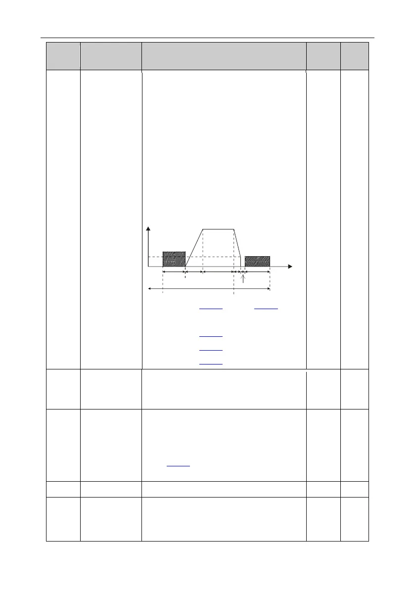
Running
command
Pre-start
braking
command
Constant speed
ON
OFF
Braking waiting time
during stop
Time t
ACC
DEC DC braking at stop
Setting range of P01.08: 0.00Hz–P00.04 (max.
output frequency)
Setting range of P01.09: 0.00–30.00s
Setting range of P01.10: 0.0–100.0%
Setting range of P01.11: 0.0–50.0s
Stop knee-point
frequency
0.00–10.00Hz
In the process of deceleration to stop, the stop
deleration curve starts after the frequency set in
this parameter is reached.
The function determines the brake release after
the running command is given, and the inverter
is in a stand-by state and waits for the delay time
set by P01.13.
Setting range: 0.00–60.00s
 Loading...

