Goodrive300-LIFT series inverter Commissioning guidelines
-83-
7. After T6, the inverter receives the stop command from the controller. With the delay of T7, the
inverter stops output and withdraws the running signal. With the delay of T8, the inverter
disconnects the contactor and the running process ends.
Note: The preceding logic is applicable to contactor and brake signal control by the inverter. For
brake and contactor control signal output, the running signal can be used for contactor control and
then the auxiliary point of the contactor and control system are serially connected for brake control.
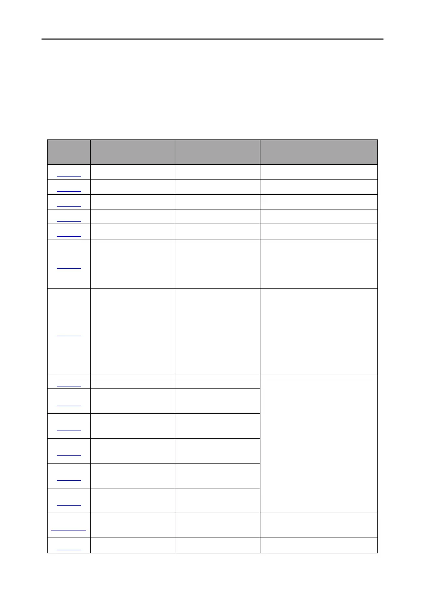
The table below lists the typical function codes for multi-step speed running.
Starting frequency of
direct startup
0.00 (closed-loop
control)
0.50 (open-loop
control)
Stop knee-point
frequency
Generally, the speed is
consistent with the leveling
speed. It is usually used to switch
the stop curve. After the speed
decreases to this point, the stop
curves switches to the stop S
curve.
According to the parameter
values on the motor name plate
Parameter value on the
motor name plate
Parameter value on the
motor name plate
Motor rated rotation
speed
Parameter value on the
motor name plate
Parameter value on the
motor name plate
Parameter value on the
motor name plate
Adjusted based on the running
conditions
 Loading...
