Goodrive30 Series VFD Communication protocol
-123-
uses a twisted pair, in which one wire is defined as A (+), and the other B (-). Generally, if the
positive electrical level between the transmission drives A and B ranges from +2 V to +6 V, the
logic is "1"; and if it ranges from -2 V to -6 V, the logic is "0".
On the VFD terminal block, the 485+ terminal corresponds to A, and 485- corresponds to B.
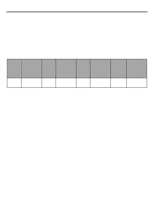
The communication baud rate (P14.01) indicates the number of bits sent in a second, and the
unit is bit/s (bps). A higher baud rate indicates faster transmission and poorer anti-interference
capability.When a twisted pair of 0.56mm (24 AWG) is used, the maximum transmission
distance varies according to the baud rate, as described in the following table.
Max.
transmissio
n distance
(meter)
Max.
transmissio
n distance
(meter)
Max.
transmissio
n distance
(meter)
Max.
transmissio
n distance
(meter)
When RS485 interfaces are used for long-distance communication, it is recommended that
you use shielded cables, and use the shielding layer as the ground wires.
When there are fewer devices and the transmission distance is short, the whole network works
well without terminal load resistors. The performance, however, degrades as the distance
increases. Therefore, it is recommended that you use a 120Ω terminal resistor when the
transmission distance is long.
7.2.1.1 When one VFD is used
Figure 7-1 is the Modbus wiring diagram for the network with one VFD and PC. Generally, PCs
do not provide RS485 interfaces, and therefore you need to convert an RS232 or USB
interface of a PC to an RS485 interface through a converter. Then, connect end A of the
RS485 interface to the 485+ port on the terminal block of the VFD, and connect end B to the
485- port. It is recommended that you use shielded twisted pairs. When an RS232-RS485
converter is used, the cable used to connect the RS232 interface of the PC and the converter
cannot be longer than 15 m. Use a short cable when possible. It is recommended that you
insert the converter directly into the PC. Similarly, when a USB-RS485 converter is used, use
a short cable when possible.
When the wiring is completed, select the correct port (for example, COM1 to connect to the
RS232-RS485 converter) for the upper computer of the PC, and keep the settings of basic
parameters such as communication baud rate and data check bit consistent with those of the
VFD.

 Loading...


