EasyManuals Logo
Home>INVT>Inverter>Goodrive30 VFD Series

INVT Goodrive30 VFD Series User Manual

INVT Goodrive30 VFD Series
175 pages
To Next Page IconTo Next Page
To Previous Page IconTo Previous Page
Page #17 background imageLoading...
Page #17 background image
Goodrive30 Series VFD Product overview
-11-
Model
Voltage
class
Output power
(kW)
Input current
(A)
Output current
(A)
GD30-090G-4
90
168
180
GD30-110G-4
110
201
215
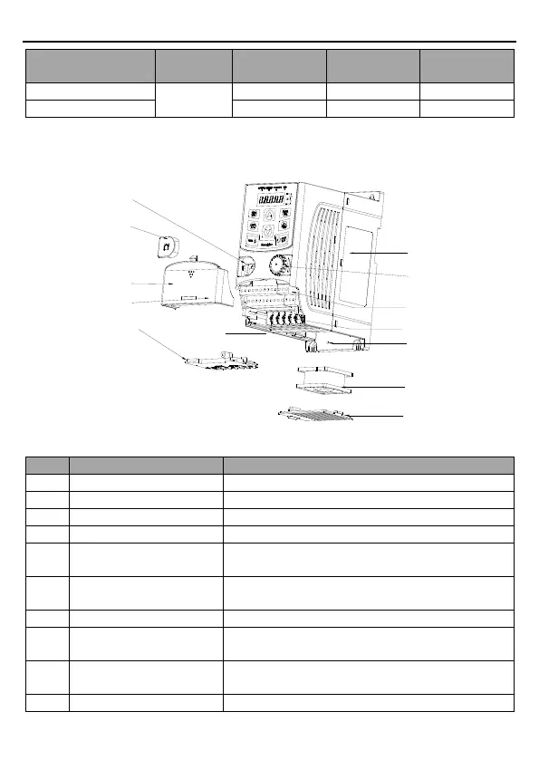
2.6 Structure diagram
The following figure shows the structure of the VFD (3PH 380V, ≤2.2kW) (using the 0.75kW
VFD model as the example).
6
12
8
10
7
3
2
5
1
9
11
4
13
Figure 2-3 Product structure (3PH 380V, ≤2.2kW)
No.
Item
Description
1
External keypad port
Connect the external keypad.
2
Port cover
Protect the external keypad port.
3
Sliding cover
Protect the internal parts and components.
4
Hole for the sliding cover
Fix the sliding cover.
5
Trunking board
Protect the inner components and fix the cables of the
main circuit.
6
Product nameplate
See section 2.3 "Product nameplate" for detailed
information.
7
Potentiometer knob
Refer to Chapter 4 "Keypad operation procedure".
8
Control terminals
See Chapter 3 "Installation guidelines" for detailed
information.
9
Main circuit terminals
See Chapter 3 "Installation guidelines" for detailed
information.
10
Screw hole
Fix the fan cover and fan.

Table of Contents

Questions and Answers:

Question and Answer IconNeed help?

Do you have a question about the INVT Goodrive30 VFD Series and is the answer not in the manual?

INVT Goodrive30 VFD Series Specifications

General IconGeneral
BrandINVT
ModelGoodrive30 VFD Series
CategoryInverter
LanguageEnglish

Related product manuals