Goodrive30 Series VFD Product overview
-12-
See Chapter 6 "Fault tracking" for detailed
information.
The same as the bar code on the name plate.
Note: The bar code is on the middle shell which is
under the cover.
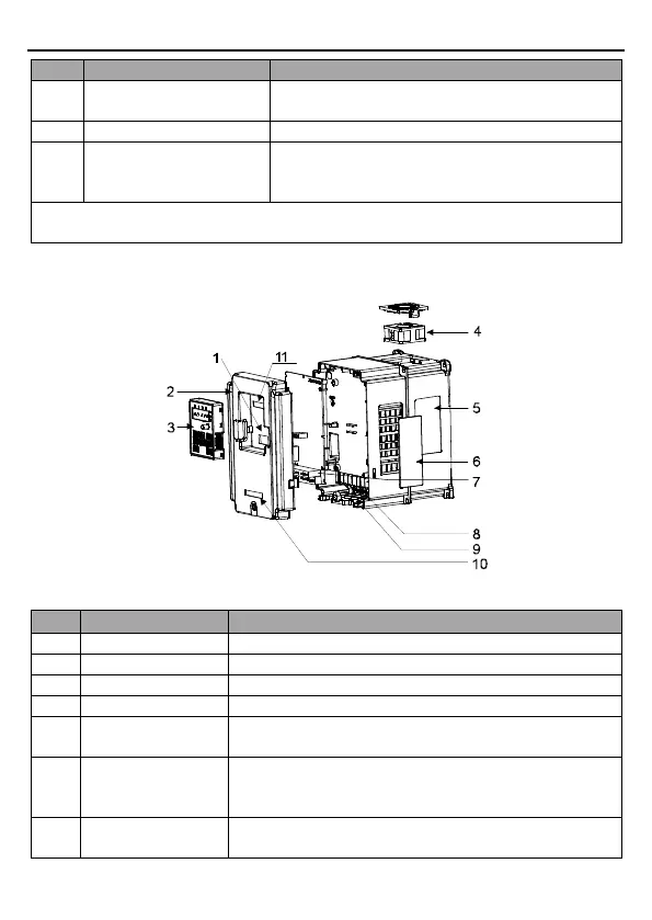
Note: In above figure, the screws at 4 and 10 are provided with packaging, and specific
installation depends on the requirements of customers.
The following figure shows the structure of the VFD (3PH 380V, ≥4kW) (using the 4kW VFD
model as the example).
Figure 2-4 Product structure (3PH 380V, ≥4kW)
Protect the internal parts and components.
Refer to Chapter 4 "Keypad operation procedure".
See Chapter 6 "Fault tracking" for detailed information.
See section 2.3 "Product nameplate" for detailed
information.
Optional. Using the ventilation hole cover can enhance the
protection rating but also increase the internal temperature,
which requires derating.
See Chapter 3 "Installation guidelines" for detailed
information.

 Loading...


