Goodrive30 Series VFD Installation guidelines
-20-
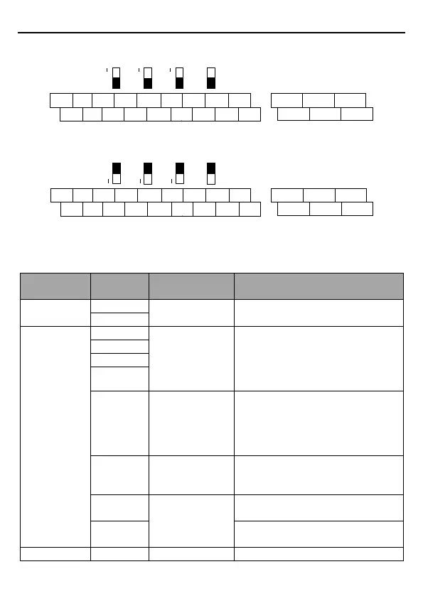
3.2.5 Control circuit terminals
ON
AO1 AO2 AI2 485
S1 S2 S3 S4 HDI Y1 AI2 AI3 +10V RO1A RO1B RO1C
RO2A RO2B RO2C+24V
PW COM COM GND AO1
AO2 485+ 485-
V V V
Figure 3-10 Control circuit terminal diagram for less than 4kW VFDs
Figure 3-11 Control circuit terminal diagram for 4kW and higher VFDs
Note: The rectangular black mark indicates the shorting cap or DIP switch ex-factory selection
position.
Function
description
Technical specifications
RS485
communication
RS485 communication terminal, using
the Modbus protocol.
Digital input
Internal impedance: 3.3kΩ
Accept 12–30V voltage input
The terminal is the bi-directional
input terminal
Max. input frequency: 1KHz
High frequency
pulse input channel
In addition to S1–S4 functions, the
terminals can also act as high
frequency pulse input channels.
Max. input frequency: 50kHz
Duty ratio: 30%–70%
Used to provide input digital working
power from the external to the internal.
Voltage range: 12–30V.
Switch capacity: 50mA/30V
Range of output frequency: 0–1kHz
Common terminal of open collector
output
Used to externally provide
ON
AO1 AO2 AI2 485
S1 S2 S3 S4 HDI Y1 AI2 AI3 +10V RO1A RO1B RO1C
RO2A RO2B RO2C+24V
PW COM COM GND AO1
AO2 485+ 485-
V V V

 Loading...


