Goodrive30 Series VFD Installation guidelines
-22-
Common contact of
relay 2
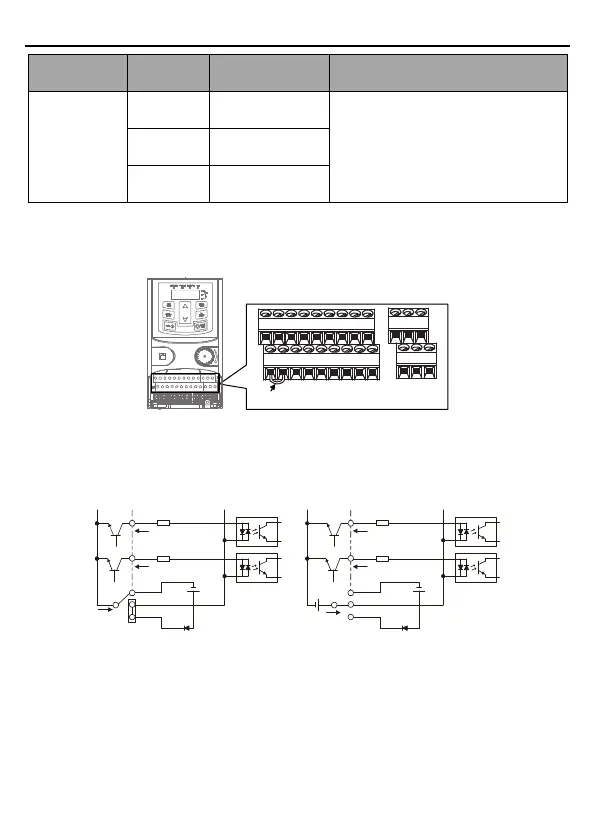
3.2.6 Input/output signal connection diagram
You can select the NPN/PNP mode and internal/external power through the U-type short
connector. NPN internal mode is adopted by default.
U-shaped tag between 24V and PW
Figure 3-12 Position of U-type short connector
If input signal comes from NPN transistors, set the U-type short connector based on the power
used according to the following figure.
S1
S2
COM
PW
+
24V
COM
+ 24V
Internal power(NPN mode)
S1
S2
COM
PW
+ 24V
COM
+
24V
External power(NPN mode)
+ 24V
Figure 3-13 NPN mode
If input signal comes from PNP transistors, set the U-type short connector based on the power
used according to the following figure.

 Loading...


