Goodrive30 Series VFD Optional peripheral accessories
-167-
C.7.2 Braking resistor installation
Braking resistor cables need to be shielded cables.
All resistors need to be installed in places with good cooling conditions. Braking resistors are
connected externally.
The materials near the braking resistor must be non-flammable. The
surface temperature of the resistor is high. Air flowing from the resistor is
of hundreds of degrees Celsius. Prevent any materials from coming into
contact with the resistor.
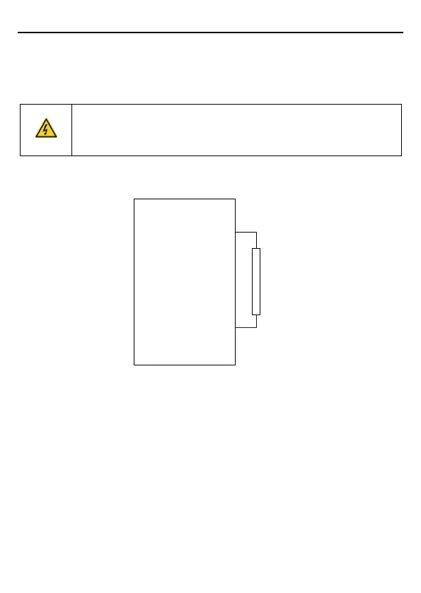
Goodrive30 series VFD need only external braking resistors. PB and (+) are the terminals for
connecting braking resistors. Installation of braking resistors is shown in the following figure.
PB
External
braking
resistor
Goodrive30
(+)

 Loading...


