Goodrive30 Series VFD Installation guidelines
-17-
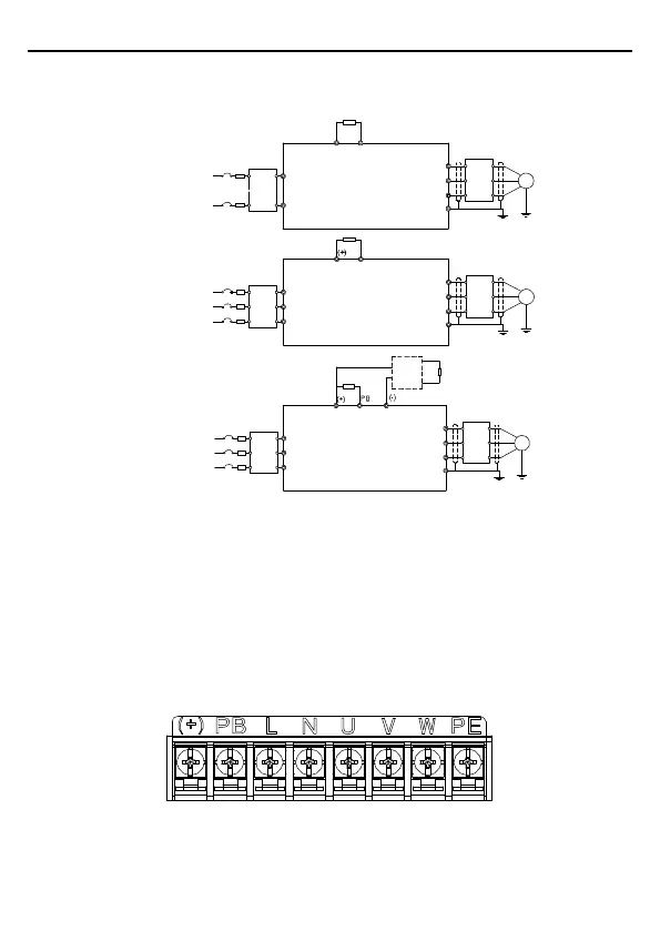
3.2 Standard wiring
3.2.1 Wiring of main circuit
Braking unit
Braking resistor
PB
(+)
Output
reactor
Output
filter
Braking resistor
PB
Output
reactor
Output
filter
Braking resistor
Input
reactor
Input
filter
Braking resistor
Input
reactor
Input
filter
Input
reactor
Input
filter
3PH 380V≤22kW
3PH 220V≤0.75kW
3PH 380V≥4kW
3PH 220V≥1.5kW
DC+
DC-
Output
reactor
Output
filter
1PH
220V(-15%)~
240V(+10%)
50/60Hz
3PH
220V(-15%)~
240V(+10%)
50/60Hz
3PH
380V(-15%)~
440V(+10%)
50/60Hz
3PH
220V(-15%)~
240V(+10%)
50/60Hz
3PH
380V(-15%)~
440V(+10%)
50/60Hz
Fuse
Fuse
Fuse
L
N
U
v
w
PE
R
S
T
U
v
w
PE
R
S
T
U
v
w
PE
M
M
M
Figure 3-3 Wiring of main circuit
Note:
The fuse, braking resistor, input reactor, input filter, output reactor, output filter are optional
parts. Please refer to Appendix C "Optional peripheral accessories" for detailed
information.
Remove the yellow warning labels of PB, (+) and (-) on the terminals before connecting
the braking resistor; otherwise, poor connection may be occur.
3.2.2 Main circuit terminals
Figure 3-4 Main circuit terminal diagram for 1PH VFD models

 Loading...


