EasyManuals Logo
Home>INVT>Inverter>Goodrive30 VFD Series

INVT Goodrive30 VFD Series User Manual

INVT Goodrive30 VFD Series
175 pages
To Next Page IconTo Next Page
To Previous Page IconTo Previous Page
Page #22 background imageLoading...
Page #22 background image
Goodrive30 Series VFD Installation guidelines
-16-
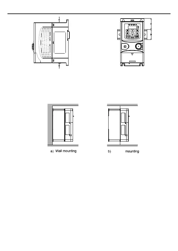
a) Wall mounting b) Rail mounting
Figure 3-1 Installation mode
Note: The minimum space of A and B is 100mm if H is 36.6mm and W is 35.0mm.
2. Wall and flange mounting for the VFDs (3PH 380V, ≥4KW and 3PH 220V, ≥1.5KW)
Flange
Figure 3-2 Installation mode
(1) Mark the position of the installation hole. Refer to Appendix B "Dimension drawings" for the
position of installation hole.
(2) Mount the screws or bolts onto the designated position.
(3) Put the VFD on the wall.
(4) Tighten the fixing screws on the wall.

Table of Contents

Questions and Answers:

Question and Answer IconNeed help?

Do you have a question about the INVT Goodrive30 VFD Series and is the answer not in the manual?

INVT Goodrive30 VFD Series Specifications

General IconGeneral
BrandINVT
ModelGoodrive30 VFD Series
CategoryInverter
LanguageEnglish

Related product manuals