Goodrive30 Series VFD Dimension drawings
-148-
Appendix B Dimension drawings
This chapter describes the dimension drawings of the VFD. The dimension unit used in the
drawings is mm.
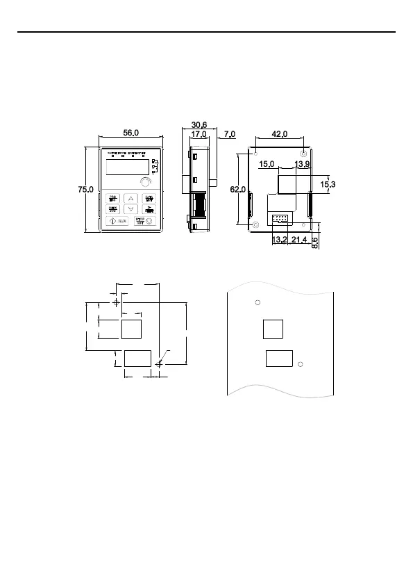
B.1 External keypad structure
Figure B-1 Keypad outer outline
42.0
5.2
62.0
19.0
17.1
48.1
19.0
16.0
26.0
8.0
2-Ø4.5
Figure B-2 Hole-cutting diagram for non-bracket keypad
Note: An external keypad is the optional part for the VFD models of 1PH 220V/3PH 380V
(≤2.2kW) and 3PH 220V (≤0.75kW). For the VFD models of 3PH 380V (≥4kW) and 3PH 220V
(≥1.5kW), the keypad can be connected externally.
When installing an external keypad, you can install it on the keypad adapter bracket which is
optional part.

 Loading...


